Table of Contents
Advertisement
Harbor Breeze® is a registered trademark
of LF, LLC. All Rights Reserved.
ATTACH YOUR RECEIPT HERE
Purchase Date
Questions, problems, missing parts? Before returning to your retailer, call our customer
service department at 1-800-643-0067, 8 a.m. - 6 p.m., EST, Monday - Thursday, 8 a.m. - 5 p.m.,
EST, Friday.
AB1801
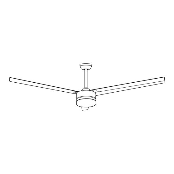
BRIDGEWATER CEILING FAN
1
ITEM #0835144
MODEL #C-TR56BNK3D1R
Français p. 19
4009654
Advertisement
Table of Contents

Related Manuals for Harbor Breeze C-TR56BNK3D1R


Summary of Contents for Harbor Breeze C-TR56BNK3D1R
- Page 1 ITEM #0835144 BRIDGEWATER CEILING FAN MODEL #C-TR56BNK3D1R Harbor Breeze® is a registered trademark Français p. 19 of LF, LLC. All Rights Reserved. 4009654 ATTACH YOUR RECEIPT HERE Purchase Date Questions, problems, missing parts? Before returning to your retailer, call our customer service department at 1-800-643-0067, 8 a.m.
-
Page 2: Table Of Contents
TABLE OF CONTENTS Safety Information ......................... 2 Package Contents ......................... 4 Hardware Contents ..........................5 Preparation ..........................5 Initial Installation ........................5 Installing Safety Cable ......................10 Wiring ...........................11 Final Installation ........................13 Operating Instructions ......................15 Care and Maintenance ......................16 Troubleshooting ........................ - Page 3 SAFETY INFORMATION WARNING WARNING When mounting fan to a ceiling outlet box, use a METAL octagonal outlet box; do NOT use a plastic outlet box. Secure the outlet box directly to the building structure. The outlet box and its support must be able to support the moving weight of the fan (at least 35 lbs.). To avoid personal injury, the use of gloves may be necessary while handling fan parts with sharp edges.
-
Page 4: Package Contents
PACKAGE CONTENTS PART DESCRIPTION QUANTITY PART DESCRIPTION QUANTITY Downrod Lock Washer (preassembled) 6 + 1 Canopy Flat Washer (preassembled) 6 + 1 Mounting Bracket LED Light Kit (preassembled) Pin (preassembled) Motor Housing Clip (preassembled) Yoke Cover Blade Canopy Mounting Washer Remote Control Receiver (preassembled) Remote Pack... -
Page 5: Hardware Contents
HARDWARE CONTENTS (shown actual size) Fitter Plate Wire Screw Connector Qty. 1 Qty. 4 PREPARATION Before beginning assembly of product, make sure all parts are present. Place motor on carpet or on foam to avoid damage to finish. Compare parts with package contents list and hardware contents list. If any part is missing or damaged, do not attempt to assemble the product. - Page 6 INITIAL INSTALLATION Determine mounting method to use. A. Standard mount B. Angle mount Note: Flushmount and closemount options are not available for this fan. IMPORTANT: If using the angle mount, ensure the ceiling angle is not steeper than 19°. 19° max. *Helpful Hint: Downrod-style mounting is best suited for ceilings 10 ft.
- Page 7 INITIAL INSTALLATION 5. Remove 6 motor screws (H), 6 lock washers (I) (Top View) and 6 flat washers (J) from top of motor housing (D). Place one blade (N) on top of motor housing (D), aligning holes in blade (N) with holes in motor housing (D).
- Page 8 INITIAL INSTALLATION Remove vice (Q) from safety cable (R) preassembled to motor housing (D) by loosening preassembled screw and nut on vice (Q). Screw Remove pin (L) and clip (M) from downrod (A). Partially loosen preassembled set screws and nuts in yoke at top of motor housing (D). Set Screw &...
- Page 9 INITIAL INSTALLATION Slip downrod (A) into yoke of motor housing (D), align holes and re-install pin (L) and clip (M). Tighten set screws and then tighten nuts. Slide yoke cover (E) down until it rests on top of motor housing (D). Set Screw and Nut Depending on the length of downrod you use, you...
-
Page 10: Installing Safety Cable
INITIAL INSTALLATION 14. Install hanging ball of downrod (A) into opening of mounting bracket (C). Align one of the slots in hanging ball with the tab in mounting bracket (C). DANGER: Failure to align slot in hanging ball with the tab in mounting bracket (C) may result in serious injury or death. -
Page 11: Wiring
WIRING GROUND (GREEN OR BARE) WHITE SUPPLY WIRE 1. Make the necessary wiring connections for GROUND remote control operation as detailed below and (GREEN OR BARE) BLACK SUPPLY WIRE in the figure. For each wire connection, use one of the wire connectors (CC), making sure to BLUE WHITE WHITE... - Page 12 WIRING Wrap electrical tape (not included) around each individual wire connector down to the wire. WARNING: Make sure no bare wire or wire strands are visible after making connections. Place GREEN and WHITE connections on opposite side of the outlet box from the BLACK and BLUE connections.
-
Page 13: Final Installation
FINAL INSTALLATION 1. Lift canopy (B) to mounting bracket (C) again, aligning slotted holes in canopy (B) with loosened canopy mounting screws (G) in mounting bracket (C). Twist canopy (B) clockwise to lock. Re-insert the two canopy mounting washers (F) and canopy mounting screws (G) previously removed (Step 4, page 6) and tighten all canopy mounting screws (G) securely. - Page 14 FINAL INSTALLATION Carefully arrange wiring within the LED light kit. Align slotted holes in LED light kit (K) with loosened screws in fitter plate. Twist LED light kit (K) to lock. Insert fitter plate screw (BB) from hardware contents and tighten all three fitter plate screws (BB) and (S) with a Phillips screwdriver.
-
Page 15: Operating Instructions
OPERATING INSTRUCTIONS CAUTION: The remote control transmitter can be programmed to multiple receivers or fans. If this is not desired, turn wall switch off to any other programmable receiver or fan. Remove battery cover from back of remote Remote control transmitter in remote pack (P). Install Control battery from remote pack (P) with positive (+) Transmitter... -
Page 16: Care And Maintenance
OPERATING INSTRUCTIONS Operation buttons on the panel of the remote control transmitter: 3 button for fan HIGH speed 2 button for fan MEDIUM speed 1 button for fan LOW speed 0 button to turn fan OFF button to turn light ON or OFF button quickly to turn lights off or on. -
Page 17: Troubleshooting
TROUBLESHOOTING WARNING: Before beginning work, shut off the power supply to avoid electrical shock. PROBLEM POSSIBLE CAUSE CORRECTIVE ACTION Fan does not move. 1. Power is off or fuse is blown. 1. Turn power on or check fuse. 2. Faulty wire connection. 2. -
Page 18: Limited Lifetime Warranty
LIMITED LIFETIME WARRANTY The distributor warrants this fan to be free from defects in workmanship and materials present at time of shipment from the factory for Lifetime limited from the date of purchase. This warranty applies only to the original purchaser. The distributor agrees to correct any defect at no charge or, at our option, replace the ceiling fan with a comparable or superior model.
Need help?
Do you have a question about the C-TR56BNK3D1R and is the answer not in the manual?
Questions and answers