Table of Contents
Advertisement
Quick Links
Advertisement
Table of Contents

Related Manuals for Crestron ST-LT


Summary of Contents for Crestron ST-LT
-
Page 3: Table Of Contents
Further Inquiries... 16 Syntax... 16 Return and Warranty Policies... 17 Merchandise Returns / Repair Service ... 17 CRESTRON Limited Warranty ... 17 Appendix: GRAFIK Eye Commands ... 18 Format for Commands... 18 GRX-AV-RS232 Command List ... 18 GRX-AV-RS232/ATC Command List ... 22 Operations Guide - Doc. -
Page 5: Lutron Interface
SmarTouch STS to interface with a Lutron GRAFIK Eye Lighting System. Future ST-LT production models shall permit an interface with the Lutron Homeworks System. If the ST-LT is part of the CRESNET II System, use of the supplied power pack is optional. - Page 6 This DC power socket connector is used to supply external power via the supplied 500 mA power pack (1000 mA power pack for the STI-LT). If the ST-LT is part of the CRESNET II System, use of the supplied power pack is optional.
- Page 7 NOTE: Most 4-conductor phone cables are wired in a crisscross fashion and are not compatible with CRESTRON equipment. If the power pack is attached when the ST-LT is part of the CRESNET II system, power is drawn from the power pack. The module does not load the network power, but the network power remains chained for additional network devices that are connected.
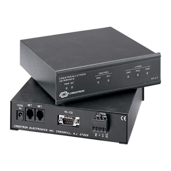
- Page 8 CRESTRON ST-LT Indicators There are seven LED indicators located on the front panel of the ST-LT. Refer to illustration and descriptions below. ST-LT Indicators PWR (Power) This LED illuminates when 12 volts (from power packs) or 24 volts DC (from network) is supplied to the ST-LT.
-
Page 9: Leading Specifications
“NET.ID” statement of the CRESNET II SIMPL-I program in order for the device to be addressed properly. The NET ID of each ST-LT has been factory set to 1C, but may be changed from the PC via STS/VTW software or the CRESNET II Workshop. - Page 10 4. Notice the list of current network devices in the dialog box. Highlight the ST-LT. 5. The factory set NET ID of the ST-LT (1C) appears in the dialog box. Use the scroll arrow to assign the new NET ID.
-
Page 11: Dip Switch Settings For Grafik Eye Use
An eight-position dip switch is mounted to the ST-LT PC board. The switch positions (switches 6 and 7 ON) are factory set for typical use of the ST-LT within a CRESNET II System or SmarTouch STS. However, in certain GRAFIK Eye systems, the switch positions may need to be altered. -
Page 12: Switch Function
SWITCH 8 • Lutron Interface CRESTRON 4. Slide the top cover toward the back panel while holding the ST-LT in place until the cover is free. 5. Locate the dip switch and notice the orientation (#1 - #8); refer to illustration below. -
Page 13: Preparation For Use
SmarTouch STS. The second diagram shows connections to the CRESNET II system. Other than making the power connection last, complete the connections in any order, regardless of whether the ST-LT is part of SmarTouch STS or the CRESNET II system. -
Page 14: Programming
STS/VTW Help menu. Use STS/VTW software (version 10.7 or higher and STS database version 10.7.100.02 or later) to include the ST-LT in lieu of a Lutron GRAFIK Eye device into a SmarTouch system. Once included, a command sequence or macro must be enabled via software. - Page 15 (SCENE or ZONE) commands. Operations Guide - Doc. 5694 CRESTRON Select Open and Project from the File menu to open the touchpanel project file. For this sample, the project has been named LUTRON.PRJ.
- Page 16 Click the Insert Command button to open the “Device Functions” dialog box. 8. Highlight the ST-LT in the Device area to display the associated functions in the right-hand column. 9. Select MAIN-UNIT-2 as the desired function. The dialog box should appear as shown below;...
- Page 17 SIMPL is CRESTRON’s programming language designed for easy implementation of the control system requirements. The best representation of SIMPL programming is the block diagram. A basic ST-LT SIMPL program is shown and described below. ST-LT SIMPL Program The sample ST-LT SIMPL program allows two scenes for the Grafik Eye; scene 2 on Main Unit 1 and scene 16 on Main Units 7 and 8.
- Page 18 ST-LT Workshop Screens (3 of 4) ST-LT Workshop Screens (4 of 4) The ST-LT is defined as an “ST-COM, Port A”. Enter “GRAFIK” into the baud rate field to allow the ST-LT to communicate with the Grafik Eye unit. The fields for parity, data bits, and stop bits are not used and may be set to any value.
-
Page 19: Operation
NOTE: Command operations denoted with an asterisk (*) are for GRX-AV-RS2323/ATC only. For a more comprehensive description of commands refer to “Appendix: GRAFIK Eye Commands” on page 18. Operations Guide - Doc. 5694 CRESTRON CMD PARAMETERS [scene][main units] :A21 select scene 2 on unit 1 :AG78 select scene 16 on units 7 &... -
Page 20: Problem Solving
Further Inquiries If after reviewing this Operations Guide for the ST-LT, you can not locate specific information, please take advantage of CRESTRON's award winning technical support team in your area. Dial one of the following numbers. For local support from exclusive Crestron factory-trained personnel in New Zealand call Amber Technologies at +649-410-8382. -
Page 21: Return And Warranty Policies
CRESTRON shall not be liable to honor the terms of this warranty if the product has been used in any application other than that for which it was intended, or if it has been subjected to misuse, accidental damage, modification, or improper installation procedures. -
Page 22: Appendix: Grafik Eye Commands
For scene 10 enter an “A”; for scene 11, enter a “B”, and so on up to scene 16. Scene numbers outside the range of 0-G return an error statement. 18 • Lutron Interface CRESTRON : A 1 2 3 ... <CR> Clear... - Page 23 ‘L’ is returned if a unit is sending a master lower. Operations Guide - Doc. 5694 CRESTRON Select scene 2 on GRAFIK Eye Main Unit 1. Select scene 16 on GRAFIK Eye Main Units 4 and 5;...
- Page 24 :ZL<CR> :ZL2<CR> :ZL+68<CR> :ZL-3<CR> 20 • Lutron Interface CRESTRON Main Unit A1 is in scene 2 Main Unit A2 is sending a master lower Main Unit A3 is OFF Main Unit A4 is missing Main Unit A5 is in scene 10...
- Page 25 This command cancels all zone raise commands. It is used as a short cut for sending the B command listing no zones and all Main Units. Operations Guide - Doc. 5694 CRESTRON Ramp down zones 1, 3, 5, and 7 of GRAFIK Eye Main Unit 1.
-
Page 26: Grx-Av-Rs232/Atc Command List
8 to the OFF position. There is only one parameter for this command, a number which selects the schedule. 22 • Lutron Interface CRESTRON Stop all zones on all GRAFIK Eye Main Units that are ramping up. - Page 27 1 and continues from that point. Operations Guide - Doc. 5694 CRESTRON 0 = no schedule active 1 = "weekday" schedule 2 = "weekend" schedule 3 = "special 1"...
- Page 28 If a super sequence is not loaded, an error statement is reported. Example: :QC<CR> 24 • Lutron Interface CRESTRON Start super sequence . Stop super sequence at the current step. Continue super sequence from the current step. Operations Guide - Doc. 5694...
- Page 29 CRESTRON This page intentionally left blank. Lutron Interface • 25 Operations Guide - Doc. 5694...
- Page 30 CRESTRON This page intentionally left blank. 26 • Lutron Interface Operations Guide - Doc. 5694...
- Page 31 CRESTRON This page intentionally left blank. Lutron Interface • 27 Operations Guide - Doc. 5694...
Need help?
Do you have a question about the ST-LT and is the answer not in the manual?
Questions and answers