Table of Contents
Advertisement
Quick Links
C2N-UNI8IO
Universal Keypad Interface
Installation & Operation Guide
Description
The Crestron
®
C2N-UNI8IO is a compact interface designed to allow virtually any keypad
to be connected directly to a Cresnet
control network. The Cresnet network is the
®
communications backbone for Crestron sensors, dimmers, keypads, touch panels,
shade controllers, thermostats, and many other devices. This exible 4-wire bus provides
data communications and 24 Vdc power for all of the devices on the Cresnet network.
The C2N-UNI8IO installs easily at the keypad location, sitting conveniently inside the
electrical box behind the keypad. Wiring connections to the network are made using a
detachable terminal block connector. Wiring connections to the keypad can be made
using the provided connectors with ying leads, or the keypad manufacturer can choose
to mate directly to the exposed connectors.
The C2N-UNI8IO is compatible with most keypads that provide contact closures as user
inputs and use LEDs for feedback. Up to 1 A @ 24 Vdc power and 40 mA @ 5 Vdc is
available to support a variety of keypads. The C2N-UNI8IO includes eight sensing inputs,
each capable of sensing a contact closure. The C2N-UNI8IO also includes eight
open-drain outputs capable of sinking up to 100 mA each (500 mA maximum total
current). Also provided are eight current-limiting resistors that can be switched in series
with each channel to limit the output current to 5 mA @ 5 Vdc.
Speci cations for the C2N-UNI8IO are listed below.
SPECIFICATION
DETAILS
Power Requirements
Cresnet Power Usage
0.5 W (0.02 A @ 24 Vdc)
Does not account for LED, bulbs, or other device's
power consumption.
Ratings
Digital Inputs
(8) Inputs rated for 0-24 Vdc, includes 10 KΩ pull-up
to 5 Vdc
Logic low threshold: ≤1 V
Logic high threshold: ≥3.7 V
Digital Outputs
(8) Open drain outputs rated for 100 mA @ 24 Vdc,
500 mA max (combined for all 8 outputs), when not
in Current Limit mode
Maximum Power Load: 1 A @ 24 Vdc and
40 mA @ 5 Vdc. Actual load capability dependent
upon the amount of available Cresnet power in the
system.
Environmental
Temperature
32°F to 104°F (0°C to 40°C)
Humidity
10% to 95% RH (noncondensing)
Dimensions
Height
2.06 in (53 mm)
Width
2.05 in (52 mm)
Depth
0.68 in (18 mm)
Weight
1 oz (24 g)
Additional Resources
Visit the product page on the Crestron website (www.crestron.com)
for additional information and the latest rmware updates. Use a QR
reader application on your mobile device to scan the QR image.
Hardware Hookup
The following diagram shows a C2N-UNI8IO in a lighting and AV system application.
Multiwire cable
C2N-UNI8IO
Third-party keypad
Cresnet
Lighting
system
Control
processor
A/V
system
Connectors, Controls, and Indicators
The following diagram shows a C2N-UNI8IO in a lighting and AV system application.
2.05 in
0.69 in
2.07 in
(52 mm)
(18 mm)
(53 mm)
0.51 in
(13 mm)
1
2
3
4
5
#
CONNECTORS,
DESCRIPTION
CONTROLS, AND
INDICATORS
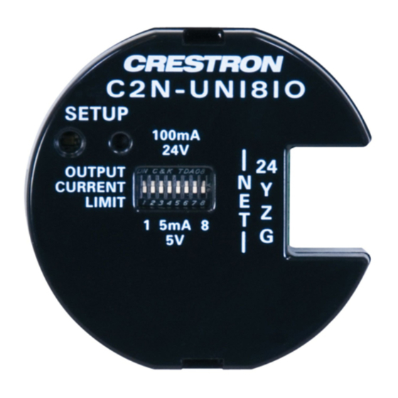
1
SETUP
(1) Red LED and (1) miniature push button, used
for touch-settable ID (TSID)
2
OUTPUT CURRENT
(1) 8-position DIP switch, engages 1 K ohm
LIMIT
current limiting resistor per output, limits each
output to 5mA @ 5VDC for use with LEDs
NOTE: When in "current limit" mode, be sure to
not exceed the above rating.
3
NET
(1) 4-pin 3.5mm detachable terminal block;
Cresnet slave port, connects to Cresnet control
network
4
OUTPUT
(1) 10-pin 0.1" IDC connector, includes (10) single
conductor 22 AWG 3" ying leads Outputs
comprised of (1) 24VDC, (1) 5VDC, and (8) digital
outputs (referenced to GND)
Note: 24V connector is a Cresnet power pass-
through.
5
INPUT
(1) 10-pin 0.1 in (3 mm) IDC connector comprised
of (10) single-conductor 22 AWG 3 in (76 mm)
ying leads
Inputs comprised of (2) GND references and (8)
digital inputs (referenced to GND)
Installation
WARNING: To avoid re, shock, or death, turn off the power at the circuit breaker or
fuse and test that the power is off before wiring!
NOTE: Observe the following points:
• Install and use this prodcut in accordance with appropriate electrical codes and
regulations.
• A licensed electrician must install this product.
NOTE: Before using the C2N-UNI8IO, ensure the device is using the latest rmware.
Check for the latest rmware for the C2N-UNI8IO at www.crestron.com/ rmware. Load
the rmware onto the device using Crestron Toolbox™ software.
The C2N-UNI8IO can be installed inside a standard electrical box. Refer to the following
illustration.
Installing the IDC Connector and the Cresnet Connector
2.13 in
Removing the IDC Connector
(54 mm)
Use a at-blade screwdriver to loosen the IDC connector from the header. Place the
at-blade screwdriver between the header and midsection of the connector. Turn the
screwdriver to pry the IDC connector up.
Using a Third-Party Keypad
Wiring Diagrams
CAUTION: Shorting non-current limited supplies may cause damage to the outputs
on the unit.
Internal 5V LED Driver (Internal 5 mA 5 V Current Limit)
NOTE
: Dip switches must be in the OFF position.
NOTE: Internal 5 mA 5 V current limit can be enabled or disabled on an individual
basis.
LED
LED
LED
LED
LED
LED
LED
LED
GND
GND
Advertisement
Table of Contents

Related Manuals for Crestron C2N-UNI8IO


Summary of Contents for Crestron C2N-UNI8IO
- Page 1 LEDs for feedback. Up to 1 A @ 24 Vdc power and 40 mA @ 5 Vdc is The C2N-UNI8IO can be installed inside a standard electrical box. Refer to the following available to support a variety of keypads. The C2N-UNI8IO includes eight sensing inputs, illustration.
- Page 2 • Increase the separation between the equipment and receiver. trademarks of Crestron Electronics, Inc. in the United States and/or other countries. UL and the UL logo This device complies with part 15 of the FCC Rules. Operation is subject to the following...
Need help?
Do you have a question about the C2N-UNI8IO and is the answer not in the manual?
Questions and answers