Table of Contents
Advertisement
Quick Links
Installation and Service Manual
PC-Series Pool Conditioner
Pool Room Dehumidifier with Air or Pool Water Heat Recovery
GEN2 Control System
Model Sizes 45-80
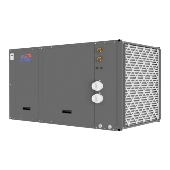
optional outdoor unit
for air conditioning
Maritime Geothermal Ltd.
info@nordicghp.com
P.O. Box 2555, 170 Plantation Road
www.nordicghp.com
Petitcodiac, NB E4Z 6H4
002291MAN-03
(506) 756-8135
ISSUE 03: 1-Oct-2021
Page 1
002291MAN-03
ISSUE 03 1-Oct-2021
Advertisement
Table of Contents

Related Manuals for Maritime Geothermal Nordic PC Series


Summary of Contents for Maritime Geothermal Nordic PC Series
- Page 1 PC-Series Pool Conditioner Pool Room Dehumidifier with Air or Pool Water Heat Recovery GEN2 Control System Model Sizes 45-80 optional outdoor unit for air conditioning Maritime Geothermal Ltd. info@nordicghp.com P.O. Box 2555, 170 Plantation Road www.nordicghp.com Petitcodiac, NB E4Z 6H4 002291MAN-03...
- Page 2 SAFETY PRECAUTIONS WARNING: Ensure all access panels are in place and properly secured before applying power to the unit. Failure to do so may cause electrical shock. WARNING: Before performing service or maintenance on the system, ensure all power sources are DISCONNECTED.
- Page 3 Version MGT GEN2 Bootload Firmware V3.66+ MGT GEN2 PC APP V2.00+ Maritime Geothermal Ltd. has a continuous improvement policy and reserves the right to modify specification data at any time without prior notice . ISSUE 03: 1-Oct-2021 Page 3 002291MAN-03...
-
Page 4: Table Of Contents
Table of Contents Tables, Figures, & Documents Setpoint Control Method 1 - Indoor Loop ......25 ......5 Setpoint Control Method 2 - External HTS/CTS ....25 System Description 2. Pool Water: Signals Control ..........25 ........... 6 General Overview ..............6 PC Application (PC App) ........ -
Page 5: Tables, Figures, & Documents
Tables, Figures, & Documents Tables Table 1 - Pool Conditioner Operating Modes (with optional AC2 outdoor condenser) ......7 Table 2 - Pool Conditioner Operating Modes (without optional AC2 outdoor condenser) ......7 Table 3 - Step by Step Pool Evaporation Rate Calculation ..............8 Table 4 - PC Typical Sizing (60 Hz) ...................... -
Page 6: System Description
Although the NORDIC AC2 and ACE outdoor units water heat exchanger is titanium/PVC for a corrosion resistance look similar, the AC2 is used with the Nordic PC series, and the that is much superior to steel, copper, or CuNi. The cabinet is... -
Page 7: Operating Mode Tables
TABLE 1 - Pool Conditioner Operating Modes (with optional AC2 outdoor condenser) AIR DEMAND (from air thermostat) POOL WATER HEAT DEMAND (from set- PC OPERATING MODE point control routine DEHUMIDIFY COOL HEAT or aquastat) POOL WATER HEAT MODE AIR REHEAT MODE POOL WATER HEAT MODE HEAT REJECTION MODE POOL WATER HEAT MODE... -
Page 8: Pc Sizing
PC Sizing Pool Surface Area TABLE 4 - PC Typical Sizing (60 Hz) Moisture Moisture As the square footage of the pool increases, the Pool Sur- Airflow Removal Removal evaporation rate will increase proportionally. This is due to the face Area Model @50%RH @60%RH... -
Page 9: Plenum Heater Sizing
TABLE 7 - Evaporation Rate Chart (50% RH) – lb/hr/ft Air Temperature (Ta) °F 0.034 0.036 0.038 0.038 0.040 0.042 0.044 0.046 0.048 0.050 0.052 0.042 0.044 0.046 0.046 0.048* 0.050 0.050 0.052 0.054 0.056 0.058 * value for recommend- 0.048 0.050 0.052... -
Page 10: Installation Basics
See diagram 002297PDG later in this manual for an example placement. OPTIONAL FROM MARITIME GEOTHERMAL The front access panels should remain clear of obstruction • ANTI-VIBRATION PAD for a distance of two feet to facilitate servicing and general •... -
Page 11: Optional Ac2 Outdoor Unit Placement
Optional AC2 Outdoor Unit Placement The optional AC2 unit must be placed outdoors, with the fan pointing away from the building. It should be at least 12 inches (30 cm) away from the building or other obstructions on the back and sides for unimpeded return airflow. There should be little or no obstruction in the fan (front) direction for at least 30 feet (9 m), otherwise airflow and therefore overall per- formance will be reduced. -
Page 12: Wiring
Wiring PC-Series Power Supply Connections Auxiliary Plenum Heater: Power Supply Connections The unit has a concentric 1.093” / 0.875” knockout for pow- er supply connection to the electrical box. There are also two Auxiliary heat for the pool room air will usually be provided 7/8”... -
Page 13: Control Transformer
Air Thermostat Connections Control Transformer The pool conditioner unit comes with its required air ther- The rest of the low voltage controls, including the control mostat, which is the BAPI Stat4 (model BA/BS4MBC-G-H2-FN- board, are powered by a 100VA class II transformer. 208/230-1 Z or close variation). -
Page 14: 002298Cdg - Typical Pc-Series Wiring Connections
ISSUE 03: 1-Oct-2021 Page 14 002291MAN-03... -
Page 15: Piping
Piping Pool Water Lines Simultaneous Pool/Hot Tub Heating The connections for the pool loop are 2” PVC unions, The following diagram 001824PDG shows two suggested rigidly fixed to the cabinet to prevent relative movement methods of heating both a pool and a hot tub with the PC unit. and possible resulting damage to interior piping. -
Page 16: 002297Pdg - Typical Loop Connections - Pc Series
ISSUE 03: 1-Oct-2021 Page 16 002291MAN-03... -
Page 17: 001824Pdg - Pc-Series Connections To Pool & Hot Tub
ISSUE 03: 1-Oct-2021 Page 17 002291MAN-03... -
Page 18: 001045Cdg - Pc-Series Cold Water Cooling Connections
ISSUE 03: 1-Oct-2021 Page 18 002291MAN-03... -
Page 19: Ductwork
A duct system capable of supplying the required air flow is to minimize evaporation from the pool surface. Large volumes of utmost importance. Maritime Geothermal Ltd. recommends of air travelling near the pool surface can also cause swimmers that the static pressure be kept below 0.2 inches of water total. -
Page 20: Figure 1 - Floor Supply Ducts With Elevated Return
FIGURE 1 - Floor Supply Ducts With Elevated Return Mechanical Room 15’ The diagram above shows a common technique for installing supply ducts in the pool room. Dry air is directed upward over the windows A, B, C and D. As the air picks up moisture from the pool room, it is drawn towards the return air grill E where it re-enters the pool conditioner. Air is released over the glass and drawn to the return air grill of the PC with as little travel as possible over the pool surface. -
Page 21: Duct Sizing Guide
TABLE 17 - Duct Sizing Guide (external static of 0.20” H Minimum Return Air Airflow Diameter Airflow Duct Area Rectangular Equivalents (in) Diameter (cfm) (in) (L/s) (sq.in) (in) 2.25 x 10 3 x 8 3.5 x 6 4 x 5.5 5 x 5 2.25 x 10 3 x 8... -
Page 22: Ac2-Series Outdoor Unit Line Set
AC2-Series Outdoor Unit Line Set Line Set Interconnect Tubing Pipe Insulation The indoor unit connections for the interconnect line set All line set piping between the indoor and outdoor units are brass service valves with flared fittings. Both lines of the should be insulated with 3/8”... -
Page 23: Charging The System
Charging the System TABLE 19 - Extra Charge Required The indoor unit is pre-charged for line sets up to 20 ft long. Extra charge required for line sets >20 ft (6 m) Once the system has been vacuumed, if extra refrigerant is required due to the length of the line set, it may be added before opening the access valves. -
Page 24: Operation
Operation BACnet Control Changing Air Setpoints Using PC App The air setpoints can also be changed through the free PC If controlling the system via the BACnet interface, skip the App software, as shown below. This requires a laptop connect- entire Operation section. -
Page 25: Pool Water Temperature Control
Pool Water Temperature Control One of the features of the PC’s GEN2 Control Board is built in aquastat functionality known as “Setpoint Control”. This is an internal routine to sample the pool water temperature to determine if pool heat is required; water temperature is meas- ured using a sensor in a well in the internal PVC piping. -
Page 26: Pc Application (Pc App)
PC Application (PC App) NOTE: Before using the PC Application, refer to Appendices for installation instructions for the PC Application and USB driver for the COM port. Both must be installed in order to run the PC App and communicate with the control board. Connect a USB cable between the PC and the control board USB connector located at the bottom center of the board. - Page 27 View Menu: This menu handles all of the operational viewing screens. Clicking on the View submenus will open the page in the PC APP’s frame. The main control panel window will open, shown below. View-->Control Panel: Equipment model information. Operational status of the system.
- Page 28 View-->Alarms, Limits and Faults The alarms page has four tabs: ALARMS - Current alarm status, alarm count, high and low refrigeration alarm cutout values, and short cycle timer. ALARMS LIST - List of alarms that have occurred since the PC APP has been operating (this will be lost when the PC is discon- nected from the control board.) LIMITS - Limits in effect which prevent compressor operation but that do not cause an alarm.
- Page 29 View-->Alarms, Limits and Faults (ALARMS LIST Tab): This tab show a history of alarms that have occurred since the PC APP was connected to the control board. This list will be lost when the PC APP is disconnected. Each alarm that occurs while This button will erase the the PC APP is connected to alarm events in the Alarm List.
- Page 30 View-->Alarms, Limits and Faults (FAULTS tab): This tab shows hardware faults that could occur. If one of these faults occurs there may be a problem with the control board hard- ware, with LCD Display and buttons, or with a sensor. If a fault occurs, some things to try: ...
- Page 31 View-->Indoor Fan Shows the settings screen for the indoor fan/blower. Airflow may be adjusted up or down by the user within the allowed range. See Indoor Airflow Data section in the Model Specific Information chapter for airflow ranges. NOTE: This screen may also be accessed from the SET button of the Indoor Fan section of the Control Panel screen.
- Page 32 Graphs Menu: This menu is a list of the available graphs. Graphs are real-time and show a time stamp of when the recording started as well as a current time which will show up if the graph is screen captured. Each graph has a CLEAR button which will erase the stored data and restart the graph.
- Page 33 Tools Menu: This is where various tools for system setup and monitoring are located. Tools-->Configuration (System Configuration tab): This is where the system setup is done. Settings should only be changed by a person who has a good understanding of system oper- ation.
- Page 34 Tools-->Configuration (Alarms and Delays tab): Click on the UP/DOWN arrows to change the value, noting that values have both a low and high limit. The number of minutes before the The minimum off time when unit can start again after various switching between heating and Count Reduce Time is alarm shutdowns...
- Page 35 Tools-->Calibration: Generally there is no need for calibration. The suction and discharge pressures may be calibrated in increments of 1 psi if there is a discrepancy in the readings when compared to a known good reference. Temperature sensors may be adjusted in increments of 0.1°F. There is an AUTO CALIBRATION routine in the program that continu- ally calibrates the temperatures sensors against an on board reference resistor by applying an offset to the temperature sensors.
- Page 36 Tools-->Datalogging (Datalog tab): The datalog rate is set via the dropdown box at the top right of the PC App main window. Starting with firmware version 2.85, a log will be recorded at the datalog rate whenever the heat pump is powered on, making it easy to compare datalogs from multiple units . The maximum number of datalog records is 32,224, which will take 45 days to fill up at the default recording rate of 2 minutes.
- Page 37 Tools-->Parameters: WARNING! The Parameters page is for advanced use only. Changing parameter values can cause the system to stop functioning properly. The parameters page shows all configurable memory spaces with their name and current value and allows them to be edited directly. To change a parameter value type in the new value and press ENTER.
-
Page 38: Lcd Interface & Menus
LCD Interface & Menus These are examples of the unit status and operating data displayed when at the message display level (top level). Pressing ENTER will enter into the menu levels beginning with the Main Menu. 2x16 LCD Display ENTER button: DOWN button: OK/EXIT button: UP button:... - Page 39 This is a list of the various tools are used for system setup and monitoring. Main Menu: The table shows what is displayed based on each press of the ENTER button starting at the Main Menu level. ENTER ENTER ENTER ENTER Description (From Main)
-
Page 40: Bacnet Interface
GND pin of the last unit. The shield grounds for intermediate units should be connected to- gether. The shield ground should be left unconnected at the building controller end for all cases. Vendor: Maritime Geothermal Ltd. Vendor ID: Model Name:... -
Page 41: Table 23 - Bacnet Objects - Data (Read Only)
TABLE 23 - BACnet OBJECTS - DATA (Read Only) Name Property Units Description Data—Type Analog Input AI0 (Comp1_Current) Present Value Amps Compressor current draw (AI0) - requires accessory AI1 (Comp2_Current) Present Value User User defined (0-5VDC or 4-20mA) Present Value User User defined (0-5VDC or 4-20mA) Present Value... -
Page 42: Table 24 - Bacnet Objects - Alarm Descriptions (Read Only)
TABLE 24 - BACnet OBJECTS - ALARM Descriptions (Read Only) Name Data Type Description AI0 (Comp1 Current) Analog Input Stage 1 Status alarm (Start / Stop Failure) - requires accessory AI1 (Comp2 Current) Analog Input LPS1 Analog Input Low pressure alarm HPS1 Analog Input High pressure alarm... -
Page 43: Table 25 - Bacnet Objects - Fault Descriptions (Read Only)
TABLE 25 - BACnet OBJECTS - FAULT Descriptions (Read Only) Name Data Type Description Analog Input AI5 (Hot Tank) Analog Input External pool water temperature sensor faulty or disconnected - requires accessory LPS1 Analog Input Low pressure sensor faulty or disconnected HPS1 Analog Input High pressure sensor faulty or disconnected... -
Page 44: Startup Procedure
A completed copy should be left on site, a copy kept on file by the installer and a copy should be sent to Maritime Geothermal Ltd. Check the boxes or fill in the data as each step is completed. For data boxes, circle the appropriate units. -
Page 45: Startup Record
1. The installer should sign and date the Startup Record and have the homeowner sign as well. The installer should leave the Startup Record with the homeowner, retain a copy for filing, and send a copy to Maritime Geothermal Ltd. for warranty registra- tion. - Page 46 Pool water temperature setpoint, delta °F °C Date: Installer Signature: Homeowner Signature: A total of three copies are required: one for the homeowner, one for the installer, and one to be sent to Maritime Geothermal Ltd. ISSUE 03: 1-Oct-2021 Page 46 002291MAN-03...
-
Page 47: Routine Maintenance
Routine Maintenance MAINTENANCE SCHEDULE WARNING: WHEN SERVICING THE OUTDOOR UNIT, BE SURE TO TURN OFF POWER TO THE INDOOR UNIT. The outdoor disconnect switch will not cut low voltage power, and damage to the control board will occur if Item Interval Procedure the main heat pump breaker is not turned off during service. -
Page 48: Troubleshooting Guide
Troubleshooting Guide WARNING: WHEN SERVICING THE OUTDOOR UNIT, BE SURE TO TURN OFF POWER TO THE INDOOR UNIT. The outdoor disconnect switch will not cut low voltage power, and damage to the control board will occur if the main heat pump breaker is not turned off during service. The following steps are for troubleshooting the pool conditioner. - Page 49 ALARM TROUBLESHOOTING Alarm/Fault Description Recommended Action The data logging function of the GEN2 Control Board is a very useful tool for troubleshooting alarms. It provides a histo- ry of the unit operation up to and including the time at which the alarm(s) occurred. Note that some alarms require ac- cessory components.
- Page 50 FAULT TROUBLESHOOTING Alarm/Fault Description Recommended Action Digital Inputs Digital Outputs Analog Inputs Cycle the power a few times; if the A failure has occurred and the indicated section of the fault persists replace the control control board may no longer work properly. MODBUS Comms board.
- Page 51 COMPRESSOR TROUBLESHOOTING Fault Possible Cause Verification Recommended Action Compressor will Faulty control board No 24vac output on STAGE1 when Replace control board. not start compressor should be operating. Faulty run capacitor Check value with capacitance meter. Replace if faulty. (single phase only) Should match label on capacitor.
- Page 52 OPERATION TROUBLESHOOTING - AIR REHEAT MODE Possible Cause Verification Recommended Action Fault Will not switch to Faulty 4-way reversing Verify solenoid by removing it from Replace solenoid if faulty. air reheat mode valve solenoid coil (RV1) the shaft while unit is running. There should be a loud “whoosh”...
- Page 53 OPERATION TROUBLESHOOTING - AIR REHEAT MODE Fault Possible Cause Verification Recommended Action High suction EEV stuck open Manually adjusting the EEV does Go to EEV troubleshooting sec- pressure not affect the superheat or the suc- tion. (may appear to tion pressure. Low superheat and not be pumping) discharge pressure.
- Page 54 OPERATION TROUBLESHOOTING - POOL WATER HEAT MODE Possible Cause Verification Recommended Action Fault High or low suc- Faulty sensor Compare pressure sensor reading Check wiring, replace sensor. If tion or discharge against a known reference such as a problem persists, replace control pressure new refrigeration manifold set.
- Page 55 OPERATION TROUBLESHOOTING - POOL WATER HEAT MODE Fault Possible Cause Verification Recommended Action High suction EEV stuck open Manually adjusting the EEV does Go to EEV troubleshooting sec- pressure not affect the superheat or the suc- tion. (may appear to tion pressure.
- Page 56 OPERATION TROUBLESHOOTING - HEAT REJECTION MODE Possible Cause Verification Recommended Action Fault Will not switch to Faulty 4-way reversing Verify solenoid by removing it from Replace solenoid if faulty. heat rejection valve solenoid coil (RV2) the shaft while unit is running. There mode should be a loud “whoosh”...
- Page 57 OPERATION TROUBLESHOOTING - HEAT REJECTION MODE Fault Possible Cause Verification Recommended Action Low suction EEV stuck almost closed Manually adjusting the EEV does Go to EEV troubleshooting sec- pressure or partially blocked by for- not affect the superheat or the suc- tion.
- Page 58 INDOOR FAN/BLOWER TROUBLESHOOTING Fault Possible Cause Verification Recommended Action Low indoor Dirty air filter Inspect. Replace. airflow Dirty air coil Inspect. Clean. Poor ductwork Measure delta T between supply The ECM fan will provide proper and return ducts at the unit. In airflow up to 0.5 inH O.
- Page 59 PLENUM HEATER TROUBLE SHOOTING Fault Possible Cause Verification Recommended Action No 230VAC Disconnect switch open Verify disconnect switch is in the ON Determine why the disconnect across plenum (if installed) position. switch was opened, if all is OK heater L1 and L2 close the switch.
- Page 60 EEV TROUBLESHOOTING If there is a refrigeration problem such as low charge, plugged filter-dryer, EEV stuck, or any other kind of restriction in the refrigeration system, the apparent EEV position will work its way towards 100% (full open). High superheat is also a symptom.
-
Page 61: Repair Procedures
Repair Procedures WARNING: WHEN SERVICING THE OUTDOOR UNIT, BE SURE TO TURN OFF POWER TO THE INDOOR UNIT. The outdoor disconnect switch will not cut low voltage power, and damage to the control board will occur if the main heat pump breaker is not turned off during service. Pumpdown Procedure 1. -
Page 62: Compressor Replacement Procedure
Compressor Replacement Procedure 1. Pump down the unit as per the Pumpdown Procedure above. If there was a compressor burn out (motor failure), the refrigerant cannot be reused and must be disposed of according to local codes. 2. Disconnect piping. 3. -
Page 63: Control Board Replacement Procedure
Control Board Replacement Procedure 1. Turn the power off to the unit. 2. Take a picture of the control board and connectors for reference. The picture in Appendix A may also be helpful. 3. Carefully remove all green terminal strips on the left side, the right side and the bottom of the control board. They pull straight off the board, with no need to disconnect wires from their screw terminals. -
Page 64: Lcd Interface (Display) Board Replacement Procedure
LCD Interface (Display) Board Replacement Procedure 1. Turn the power off to the unit. 2. Remove the display board cable connector from the control board. 3. Using a sharp utility knife with a long blade, slice each of the display board standoff heads off, taking care to not damage the lexan cover. -
Page 65: Model Specific Information
Model Specific Information Table 26 - Shipping Information (PC) Table 27 - Shipping Information (AC2 Outdoor Unit) WEIGHT DIMENSIONS in (cm) WEIGHT DIMENSIONS in (cm) MODEL MODEL lb. (kg) lb. (kg) PC-45 515 (234) 70 (178) 44 (112) 40 (102) AC2-45 230 (104) 36 (91) -
Page 66: Capacity Ratings
Capacity Ratings TABLE 33 - PC-Series Capacity Ratings (60Hz) Moisture Moisture Indoor (Pool) Indoor (Pool) Input Typical Pool Airflow Capacity Removal Removal Flow Pressure Drop Energy Surface Area Model @ 50%RH @ 60%RH psi (kPa) cfm (L/s) Watts Btu/hr (kW) lb(kg) / hr lb(kg) / hr PC-45... -
Page 67: Electrical Specifications
Electrical Specifications TABLE 35 - PC-Series Electrical Data Maximum Minimum Power Supply Compressor Nomenclature Fuse/Breaker Wire Size Identifier V-ø-Hz Amps Amps Amps 230-1-60 15.4 19.6 23.0 #8-2 208-3-60 10.4 14.1 16.7 #10-3 PC-45 460-3-60 11.0 #14-3 220-1-50 13.5 17.2 20.6 #10-2 380-3-50 10.5... -
Page 68: Indoor Airflow
Indoor Airflow TABLE 37 - Indoor Airflow Airflow Reduction Airflow Reduction Airflow Reduction Airflow Reduction Nominal Range Model - 20% - 15% - 10% - 5% Size 1150 900-1400 430-660 1040 1090 1500 1200-1800 570-850 1200 1280 1350 1430 1900 1500-2300 710-1090 1520... -
Page 69: Wiring Diagram (208/230-1-60)
Wiring Diagram (208/230-1-60) ISSUE 03: 1-Oct-2021 Page 69 002291MAN-03... -
Page 70: Electrical Box Layout (208/230-1-60)
Electrical Box Layout (208/230-1-60) ISSUE 03: 1-Oct-2021 Page 70 002291MAN-03... -
Page 71: Wiring Diagram (208-3-60)
Wiring Diagram (208-3-60) ISSUE 03: 1-Oct-2021 Page 71 002291MAN-03... -
Page 72: Electrical Box Layout (208-3-60)
Electrical Box Layout (208-3-60) ISSUE 03: 1-Oct-2021 Page 72 002291MAN-03... -
Page 73: Wiring Diagram (460-3-60)
Wiring Diagram (460-3-60) ISSUE 03: 1-Oct-2021 Page 73 002291MAN-03... -
Page 74: Electrical Box Layout (460-3-60)
Electrical Box Layout (460-3-60) ISSUE 03: 1-Oct-2021 Page 74 002291MAN-03... -
Page 75: Wiring Diagram (220-1-50)
Wiring Diagram (220-1-50) ISSUE 03: 1-Oct-2021 Page 75 002291MAN-03... -
Page 76: Electrical Box Layout (220-1-50)
Electrical Box Layout (220-1-50) ISSUE 03: 1-Oct-2021 Page 76 002291MAN-03... -
Page 77: Wiring Diagram (380-3-50)
Wiring Diagram (380-3-50) ISSUE 03: 1-Oct-2021 Page 77 002291MAN-03... -
Page 78: Electrical Box Layout (380-3-50)
Electrical Box Layout (380-3-50) ISSUE 03: 1-Oct-2021 Page 78 002291MAN-03... -
Page 79: Ac2 (Outdoor Condenser) Wiring Diagrams
AC2-45/55 Wiring Diagram AC2-65/75/80 Wiring Diagram ISSUE 03: 1-Oct-2021 Page 79 002291MAN-03... -
Page 80: Pc-Series Refrigeration Circuit - Pool Water Heat Mode
ISSUE 03: 1-Oct-2021 Page 80 002291MAN-03... -
Page 81: Pc-Series Refrigeration Circuit - Air Reheat Mode
ISSUE 03: 1-Oct-2021 Page 81 002291MAN-03... -
Page 82: Pc-Series Refrigeration Circuit - Heat Rejection Mode
ISSUE 03: 1-Oct-2021 Page 82 002291MAN-03... -
Page 83: Dimensions
Dimensions: PC (All Model Sizes) Dimensions: AC2-45/55 Dimensions: AC2-65/75/80 ISSUE 03: 1-Oct-2021 Page 83 002291MAN-03... -
Page 84: Appendix A: Control Board Description
Appendix A - GEN2 Control Board Description The picture below shows the locations of the connectors and LED indicators of the control board. The control board offers many fea- tures such as short circuit protection on all digital outputs, Real Time Clock with super capacitor for backup power, WiFi capability, relay outputs for plenum heater control (if equipped), USB port, PIC32 microcontroller, etc. -
Page 85: Table A1 - Control Board Connector Descriptions (Top)
The tables describe the connections starting with the top of the board and working around the board counter clock-wise. TABLE A1 - Control Board Connector Descriptions (Top) Signal Description HPS1 High Pressure Sensor 1 Measures compressor discharge pressure. LPS1 Low Pressure Sensor 1 Measures compressor suction pressure. -
Page 86: Table A3 - Control Board Connector Descriptions (Bottom)
TABLE A3 - Control Board Connector Descriptions (Bottom) Name Description BACnet MS/TP Ground for shield if required. BACnet MS/TP RS-485 for BACnet communication. BACnet MS/TP RS-485 for BACnet communication. STAGE1 Compressor Stage 1 Starts / stops the compressor. STAGE2 Compressor Stage 2 Not used. -
Page 87: Table A4 - Control Board Connector Descriptions (Right Side)
TABLE A4 - Control Board Connector Descriptions (Right Side) Signal Description DI_1 Digital Input1 24vac input for detection of optional outdoor unit. DI_0 Digital Input0 Not used. Phase Monitor2 Not used. Phase Monitor1 Not used. Y2A* Aquastat Stage2 Not used. Aquastat Power (24VAC) Used only for external aquastat control *. -
Page 88: Appendix B: Usb Driver Installation
Appendix B - USB Driver Installation The first step in connecting a Windows laptop computer to the 4. In the window that is displayed, click and hold down the mouse button on the folder name, and drag to your desktop: control board is to install the USB driver. -
Page 89: Appendix C: Pc App Installation
Appendix C - PC App Installation The PC App allows detailed interfacing with the control board 4. In the window that is displayed, click and hold down the mouse button on the folder name, and drag to your desktop: using a Windows laptop computer. Any Windows from XP and onwards should be compatible, but Windows 10 (as found on any recent laptop computer) is recommended. -
Page 90: Appendix D: Updating Firmware
Appendix D: Updating Firmware METHOD 1: Updating Firmware Using PC App This method can be used when updating newer control boards 7. Click on YES. The following message box will appear: with bootloader version 2.0. This method will not work for older control boards with bootloader version 1.0 (approx. - Page 91 12. Click on Load Hex File. Select the 16. Close the PIC32 program. MGL_GEN2_V366.production.hex (or higher version num- ber) file, which is in the folder you created on the Desktop. 17. WAIT APPROXIMATELY 10 SECONDS. This gives the control board time to reset, initialize and re-connect to the PC USB port.
-
Page 92: Updating Firmware Using Jumper Pins
METHOD 2: Updating Firmware Using Jumper Pins This method should be used when updating older control boards 6. Turn the power back on. The control board is now in boot that have bootloader version 1.0, or where the PC App has trou- loader mode and is ready to be programmed. -
Page 93: Warranty
COMMERCIAL LIMITED EXPRESS WARRANTY Unless a statement is specifically identified as a warranty, statements made by Maritime Geothermal Ltd. (“MG”) or its representatives relating to MG’s products, whether oral, written or contained in any sales literature, catalogue or agreement, are not express warranties and do not form a part of the basis of the bargain, but are merely MG’s opinion or commendation of MG’s products.
Need help?
Do you have a question about the Nordic PC Series and is the answer not in the manual?
Questions and answers