
Subscribe to Our Youtube Channel
Related Manuals for Crestron IM-WCVI


Summary of Contents for Crestron IM-WCVI
- Page 1 Crestron IM-WCVI iMedia Wall Plate Computer Center with Video Interface Operations & Installation Guide...
- Page 2 This document was prepared and written by the Technical Documentation department at: Crestron Electronics, Inc. 15 Volvo Drive Rockleigh, NJ 07647 1-888-CRESTRON All brand names, product names and trademarks are the property of their respective owners. ©2006 Crestron Electronics, Inc.
-
Page 3: Table Of Contents
Crestron IM-WCVI iMedia Wall Plate Computer Center with Video Interface Contents iMedia Wall Plate Computer Center with Video Interface: IM-WCVI Introduction ... 1 Features and Functions ... 1 Application ... 2 Specifications ... 3 Physical Description... 4 Industry Compliance ... 6 Setup ... -
Page 5: Imedia Wall Plate Computer Center With Video Interface: Im-Wcvi
• Mounts in a standard, 2½ inch deep, double-gang electrical box The IM-WCVI is part of the IM-WCCV-S. It must be used with the IM-WCVP. For more information on CresCAT-IM cable, refer to “IM Wiring” on page 7. For iMedia use CresCAT-IM cable, or quality CAT5e/CAT6 cable having a maximum delay skew of 15ns per 100m. -
Page 6: Application
Application The IM-WCVI is part of the IM-WCCV-S iMedia transmitter. As shown in the following diagram, iMedia transmitters provide input points for video and PC sources on an iMedia receiver. -
Page 7: Specifications
Crestron IM-WCVI iMedia Wall Plate Computer Center with Video Interface Specifications Specifications for the IM-WCVI are listed in the following table. IM-WCVI Specifications Operations & Installation Guide – DOC. 6488 SPECIFICATION Video Formats RGBHV (VGA), RGBS, RGsB, composite RGB Video... -
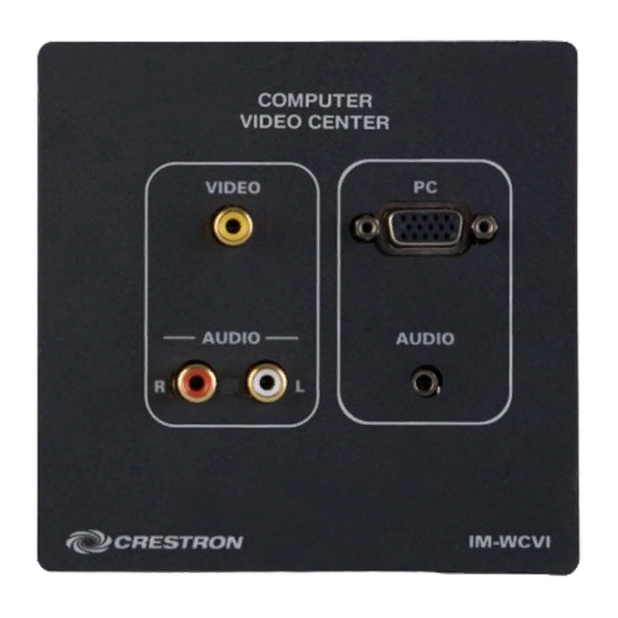
Page 8: Physical Description
This section provides information on the connections, controls, and indicators available on your IM-WCVI. IM-WCVI Physical View IM-WCVI Overall Dimensions 4 • iMedia Wall Plate Interface: IM-WCVI 4.56 in. (11.58 cm) Operations & Installation Guide – DOC. 6488 Crestron IM-WCVI 2.28 in. - Page 9 Connect the flying lead to earth ground. DESCRIPTION FUNCTION FUNCTION Red Video No Connect Green Video Ground Blue Video No Connect Reserved Monitor Sense Ground Horizontal Sync Red Ground Vertical Sync Green Ground Monitor Sense Blue Ground iMedia Wall Plate Interface: IM-WCVI • 5...
-
Page 10: Industry Compliance
Wall Plate Computer Center with Video Interface Industry Compliance As of the date of manufacture, the IM-WCVI has been tested and found to comply with specifications for CE marking and standards per EMC and Radiocommunications Compliance Labelling. NOTE: This device complies with part 15 of the FCC rules. Operation is subject to... -
Page 11: Setup
Routing CresCAT-IM cable (low-skew CAT5e) is less expensive and a much simpler solution for the wiring of iMedia systems than routing multi-colored, multi- conductor coax cable. All Crestron products using the iMedia transport system are capable of sending and receiving iMedia signals via CresCAT-IM cable. Installation of any iMedia device is as simple as installing one iMedia cable from output to input. - Page 12 15 ns per 100 m is not exceeded. NOTE: For proper operations and performance of every iMedia system, always use CresCAT-IM cable. Maximum Resolution and Cable Length (Continued on following page) 8 • iMedia Wall Plate Interface: IM-WCVI RJ-45 Male Connector RJ-45 Number RESOLUTION...
-
Page 13: Composite Video
Wall Plate Computer Center with Video Interface Maximum Resolution and Cable Length (Continued) Installation The IM-WCVI is designed to mount in a standard 2.5-inch (6.35 cm) deep, double- gang, electrical box. Required Tools: Mounting Parts Supplied with the IM-WCVI... -
Page 14: Hardware Hookup
CRESCAT-IM cable, available from Crestron. Other high-quality/low skew CAT5e/CAT6 wiring may also be used with varying performance. The maximum cable length between the IM-WCVP and the IM-WCVI is 40 feet. Hardware Connections for the IM-WCVI (Front) 10 • iMedia Wall Plate Interface: IM-WCVI... -
Page 15: System Configuration
Wall Plate Computer Center with Video Interface System Configuration Refer to the latest version of the IM-RXV1 & IM-RXV3 guide (Doc. 6478), available from the Crestron website (http://www.crestron.com/manuals) for iMedia system configuration instructions. Operations & Installation Guide – DOC. 6488... -
Page 16: Operation
Wall Plate Computer Center with Video Interface Operation For operation instructions, refer to the latest version of the IM-WCVP guide (Doc. 6489) which is available for download from the Crestron website. 12 • iMedia Wall Plate Interface: IM-WCVI Crestron IM-WCVI... -
Page 17: Problem Solving
Wall Plate Computer Center with Video Interface Problem Solving Troubleshooting The following table provides corrective action for possible trouble situations. If further assistance is required, please contact a Crestron customer service representative. IM-WCVI Troubleshooting Operations & Installation Guide – DOC. 6488... -
Page 18: Reference Documents
For assistance in your local time zone, refer to the Crestron website (http://www.crestron.com/) for a listing of Crestron worldwide offices. You can also log onto the online help section of the Crestron website to ask questions about Crestron products. First-time users will need to establish a user account to fully benefit from all available features. -
Page 19: Return And Warranty Policies
Purchasers should inquire of the dealer regarding the nature and extent of the dealer's warranty, if any. CRESTRON shall not be liable to honor the terms of this warranty if the product has been used in any application other than that for which it was intended, or if it has been subjected to misuse, accidental damage, modification, or improper installation procedures. - Page 20 Crestron Electronics, Inc. Operations & Installation Guide – DOC. 6488 15 Volvo Drive Rockleigh, NJ 07647 (2015096) Tel: 888.CRESTRON 05.06 Fax: 201.767.7576 Specifications subject to www.crestron.com change without notice.
Need help?
Do you have a question about the IM-WCVI and is the answer not in the manual?
Questions and answers