
Related Manuals for BUSCH R5 PLUS


Summary of Contents for BUSCH R5 PLUS
- Page 1 Pump Control Instructions R5 PLUS / COBRA PLUS R5 RA 0760 A PLUS, R5 RA 1000-1600 A PLUS COBRA NX 0950 A PLUS 0870213261/-0004_en / Original instructions / Modifications reserved 16/09/2021...
-
Page 2: Table Of Contents
10.4 Warning / Alarms......................30 10.5 Status Registers (Read only) ..................... 32 10.6 Advanced Status Bits (Read only) ..................33 10.7 Advanced Registers (Read only) ..................34 11 Data Logger ..........................35 2 / 40 Pump Control Instructions R5 PLUS - COBRA PLUS_EN_en... -
Page 3: Safety
... indicates a potentially dangerous situation that could result in damage to property. NOTE ... indicates helpful tips and recommendations, as well as information for efficient and trouble-free operation. Pump Control Instructions R5 PLUS - COBRA PLUS_EN_en 3 / 40... -
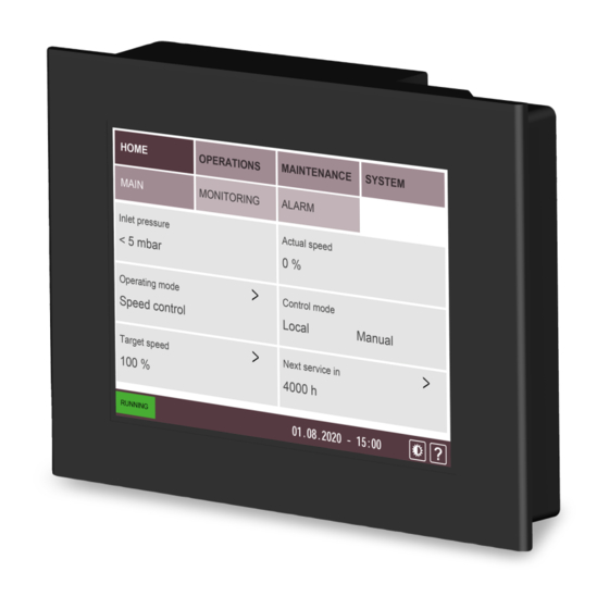
Page 4: Introduction
R5 RA 0760 A PLUS & RA 1000-1600 A PLUS vacuum pumps. Some of these displays may differ for the COBRA NX 0950 A PLUS vacuum pump. The principles of using of the interface however are similar. 4 / 40 Pump Control Instructions R5 PLUS - COBRA PLUS_EN_en... -
Page 5: Role And User
– set the remote control and monitoring parameters, refer to the specific document "Pump Control Instructions, art. no.: 0870213261". – Role 3 ► Busch Service Only authorized personnel from Busch Service have this level of access rights. NOTE In case of any questions related to the machine settings: •... -
Page 6: Warnings And Alarms Thresholds
NOTICE Change factory settings. Risk of damage to the machine! If wrong or not allowed parameters have been set, Busch disclaims any liability for dam- age to the machine. • Only change parameters after Busch approval. To consult or change thresholds values: •... - Page 7 Stop in case of alarm Warning Alarm temperature 30 s 60 s Exhaust pressure sensor disconnected Oil temperature sensor disconnected Stop in case of alarm Stop in case of alarm PREVIOUS NEXT Pump Control Instructions R5 PLUS - COBRA PLUS_EN_en 7 / 40...
- Page 8 60 mbar PREVIOUS Screen 4 SYSTEM MAINTENANCE HOME OPERATIONS SETTINGS MODEL ETHERNET CONTACT Communication loss with Frequency Frequency converter alarm converter Stop in case of alarm Auto-reset activation PREVIOUS 8 / 40 Pump Control Instructions R5 PLUS - COBRA PLUS_EN_en...
- Page 9 Pump temperature >65°C >70°C Exhaust pressure >150 hPa g (mbar g) rel. >200 hPa g (mbar g) rel. Electrical cabinet temperature >50°C for 30 seconds >50°C for 60 seconds Pump Control Instructions R5 PLUS - COBRA PLUS_EN_en 9 / 40...
-
Page 10: Advanced Settings
NOTICE Change factory settings. Risk of damage to the machine! If wrong or not allowed parameters have been set, Busch disclaims any liability for dam- age to the machine. • Only change parameters after Busch approval. To consult or change advanced settings values: •... - Page 11 • If the new sensor has a measurement accuracy of 0.1 mbar or better, switch ON the “High accuracy sensor” button. The display of the inlet pressure on the main screen will be modified as follows: Pump Control Instructions R5 PLUS - COBRA PLUS_EN_en 11 / 40...
- Page 12 If non suitable sensors are used or if the sensors are not properly configured and con- nected to the control unit, Busch disclaims any liability for damages to the machine. • Only linear sensors are supported. Logarithmic sensors are not supported. For more information contact Busch.
- Page 13 1600 mbar g PREVIOUS NEXT Trigger temperature of cooling fan (R5 PLUS with cabinet only) • The cooling fan trigger temperature can be set in the range of 40°C to 75°C. The de- fault setting is 60°C. • The increase of the trigger temperature prevents water condensation in the vacuum pump in the event of water vapor in the process gas.
- Page 14 If non suitable sensors are used or if the sensors are not properly configured and con- nected to the control unit, Busch disclaims any liability for damages to the machine. • Only linear sensors are supported. Logarithmic sensors are not supported. For more information contact Busch.
- Page 15 • Switch ON the PLUS Master control button to activate this function. Pump Control Instructions R5 PLUS - COBRA PLUS_EN_en 15 / 40...
- Page 16 – Start the process and set the required target pressure. – Click on the value(s) to be modified (PID, switching pressure between the two sets of parameters) and type the new value(s). 16 / 40 Pump Control Instructions R5 PLUS - COBRA PLUS_EN_en...
- Page 17 Selecting inappropriate PID settings can affect system performance. • Make sure that the pressure control is effective at each step of the process and restore factory settings if necessary. Pump Control Instructions R5 PLUS - COBRA PLUS_EN_en 17 / 40...
-
Page 18: Service Interval Configuration
NOTICE Change factory settings. Risk of damage to the machine! If wrong or not allowed parameters have been set, Busch disclaims any liability for dam- age to the machine. • Only change parameters after Busch approval. To change maintenance intervals: •... -
Page 19: Remote Control
Remote Analog speed control Modbus control PREVIOUS NOTE Analog or digital modes allow the control of the machine speed. Remote mode allows full control and monitoring of the machine. Pump Control Instructions R5 PLUS - COBRA PLUS_EN_en 19 / 40... -
Page 20: Start / Stop
Digital speed control Remote Analog speed control Modbus control • Connect your system to the terminal board located inside the control unit. • Consult the chapter Terminal Board Schematic [► 26]. 20 / 40 Pump Control Instructions R5 PLUS - COBRA PLUS_EN_en... -
Page 21: Analog Speed Control
• Consult the chapter Modbus Parameters [► 26]. NOTE Monitoring via Modbus. Do not activate Remote/Modbus for sole monitoring purpose. This mode is only activated if the machine is fully controlled via Modbus. Pump Control Instructions R5 PLUS - COBRA PLUS_EN_en 21 / 40... -
Page 22: Plus Master
• Any pump can be chosen as “PLUS Master”. As the control interface of the PLUS sys- tem appears only on the touchscreen of the Master pump, it is advisable to select the pump that is most easily accessible. 22 / 40 Pump Control Instructions R5 PLUS - COBRA PLUS_EN_en... -
Page 23: Plus Controlled
This mode is only available when the “PLUS Master control” function is activated in the advanced pump settings, see Advanced Settings [► 10] / Screen 3. This mode allows the pump to be set as “PLUS Controlled pump” in a PLUS system. Pump Control Instructions R5 PLUS - COBRA PLUS_EN_en 23 / 40... - Page 24 Ethernet connection. A total number of 2 to 6 PLUS pumps is supported. • For more information, please refer to the specific “PLUS Master control” instruction manual, art. no. 0870232791. 24 / 40 Pump Control Instructions R5 PLUS - COBRA PLUS_EN_en...
-
Page 25: Ethernet Settings
Ethernet connection is necessary. Description Default value IP address 192.168.0.22 Subnet mask 255.255.255.0 Gateway 192.168.0.1 PLC port (0-65535) 502 (cannot be changed) PLC Slave no. 247 (F7) (cannot be changed) Pump Control Instructions R5 PLUS - COBRA PLUS_EN_en 25 / 40... -
Page 26: Terminal Board Schematic
The default ethernet settings are the following: Description Default value IP address 192.168.0.22 Subnet mask 255.255.255.0 Gateway 192.168.0.1 PLC port (0-65535) 502 (cannot be changed) PLC Slave no. 247 (F7) (cannot be changed) 26 / 40 Pump Control Instructions R5 PLUS - COBRA PLUS_EN_en... -
Page 27: Control Bits (Read / Write)
Read Multiple Holding Registers 6 (6) Write Single Holding Register 16 (10) Write Multiple Holding Registers Below, the Busch PLC outputs (Master Client Modbus ► Read ► Slave Busch PLC Mod- bus). Supported commands (holding registers only): Function Code, Dec (Hex) Function... -
Page 28: Control Registers (Read / Write)
LSB preset Customer Speed (Digitale Input 0, for Remote) ; True = active MSB preset Customer Speed (Digitale Input 1, for Re- mote) ; True = active RESERVE RESERVE RESERVE RESERVE RESERVE MSB (bit 15) RESERVE 28 / 40 Pump Control Instructions R5 PLUS - COBRA PLUS_EN_en... - Page 29 High accuracy inlet pressure sensor activation ; True = one digit after the comma RESERVE RESERVE RESERVE RESERVE RESERVE RESERVE RESERVE RESERVE RESERVE RESERVE RESERVE MSB (bit 15) RESERVE Pump Control Instructions R5 PLUS - COBRA PLUS_EN_en 29 / 40...
-
Page 30: Warning / Alarms
Alarm: Analog input disconnected; True = Alarm Alarm: Modbus Ethernet port 1 disconnected ; True = Alarm MSB (bit 15) Alarm: External inlet pressure sensor disconnected ; True = Alarm 30 / 40 Pump Control Instructions R5 PLUS - COBRA PLUS_EN_en... - Page 31 Alarm: No mode remote selected ; True = Alarm RESERVE RESERVE RESERVE RESERVE RESERVE RESERVE RESERVE RESERVE MSB (bit 15) RESERVE * only applicable to COBRA NX 0950 A PLUS Pump Control Instructions R5 PLUS - COBRA PLUS_EN_en 31 / 40...
-
Page 32: Status Registers (Read Only)
Running hours since last maintenance [h] Low Word High Word Running hours total [h] Low Word Energy consumption since last reset [kWh] Energy consumption total [kWh] Next overhaul [months] 32 / 40 Pump Control Instructions R5 PLUS - COBRA PLUS_EN_en... -
Page 33: Advanced Status Bits (Read Only)
Trip on Inlet pressure alarm: ON ; True = Event Trip on Inlet pressure sensor disc. alarm: ON ; True = Event MSB (bit 15) Trip on Oil temperature alarm: ON ; True = Event Pump Control Instructions R5 PLUS - COBRA PLUS_EN_en 33 / 40... -
Page 34: Advanced Registers (Read Only)
Diag byte oil temperature sensor 0: Normal, 6: Wiring error (input A low limit exceeded). Diag byte exhaust pressure sensor 0: Normal, 6: Wiring error (input A low limit exceeded). 34 / 40 Pump Control Instructions R5 PLUS - COBRA PLUS_EN_en... -
Page 35: Data Logger
• Check the ethernet settings of the computer network (Internet Protocol Version 4 (TCP/IPv4) Properties). The Subnet mask and the first 3 bytes of the IP address must be the same as on the PLUS machine. Pump Control Instructions R5 PLUS - COBRA PLUS_EN_en 35 / 40... - Page 36 • Switch off the power supply of the machine. • Open the door of the control unit cabinet and take the SD card out of the Programa- ble logic controller (PLC1). 36 / 40 Pump Control Instructions R5 PLUS - COBRA PLUS_EN_en...
- Page 37 PLC, so that the operating data of the machine can be saved once it has been restart- NOTICE • For the electrical connection, please refer to the chapter Electrical Connection in the original instruction manual of the corresponding machine. Pump Control Instructions R5 PLUS - COBRA PLUS_EN_en 37 / 40...
- Page 38 Note...
- Page 39 Note...
- Page 40 Busch Vacuum Solutions We shape vacuum for you. Argentina Denmark Malaysia South Africa info@busch.com.ar info@busch.dk busch@busch.com.my info@busch.co.za Australia Finland Mexico Spain sales@busch.com.au info@busch.fi info@busch.com.mx contacto@buschiberica.es Austria France Netherlands Sweden busch@busch.at busch@busch.fr info@busch.nl info@busch.se Bangladesh Germany New Zealand Switzerland sales@busch.com.bd info@busch.de sales@busch.co.nz...
Need help?
Do you have a question about the R5 PLUS and is the answer not in the manual?
Questions and answers