Table of Contents
Advertisement
Quick Links
Advertisement
Table of Contents

Subscribe to Our Youtube Channel
Related Manuals for BUSCH 0987 209 539


Summary of Contents for BUSCH 0987 209 539
- Page 1 Pump Control Instructions R5 / COBRA with Variable-Frequency Drive R5 RA/RC 0630 B/C COBRA NC 0630 C / NX 0650 A / NX 0950 A Ateliers Busch S.A. Zone industrielle, 2906 Chevenez Switzerland 0870208958/-0002_en / Original instructions / Modifications reserved 15/02/2021...
-
Page 2: Table Of Contents
Table of Contents Table of Contents 1 Safety ............................3 2 Introduction ..........................4 3 Product Description ........................5 3.1 Scope of Delivery ......................5 3.2 Application........................5 4 Installation..........................6 4.1 Remote Control Connection ..................... 6 4.2 PC-Software Installation ....................6 5 Commissioning.........................7 5.1 Operate the Remote Control .................... -
Page 3: Safety
Prior to handling the product, this document should be read and understood. If anything needs to be clarified please con- tact your Busch representative. Read carefully before use and keep for future reference. -
Page 4: Introduction
2 | Introduction Introduction NOTE Pump control instructions. This document is delivered along with variable-frequency drive control device. It only contains information about the variable-frequency drive parametrisation and con- trol. Please refer to the original instruction manual of the corresponding machine which con- tent remains valid. -
Page 5: Product Description
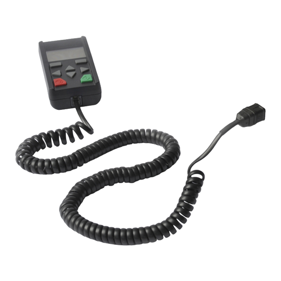
Product Description | 3 Product Description 3.1 Scope of Delivery Parameter kit Kit number: 0987 209 539 Pos. 1 Pos. 2 Pos. 3 Pos. Part Part no. Remote control including cable to vari- 0987 208 729 able-frequency drive Cable for PC... -
Page 6: Installation
4 | Installation Installation 4.1 Remote Control Connection NOTICE Non-compatible variable-frequency drive. Risk of damage to the variable-frequency drive! • The remote control must only be operated with „INVEOR“ variable-frequency drive. M12 interface socket • Connect the cable of the remote control to the M12 interface socket. 4.2 PC-Software Installation •... -
Page 7: Commissioning
Commissioning | 5 Commissioning 5.1 Operate the Remote Control 5.1.1 Key Overview Confirm buttons “UP” and “DOWN” buttons “LEFT” and “RIGHT” buttons Stop button Start button 5.1.2 Navigation and Input Buttons Function "UP"/"DOWN" buttons Selecting parameters, changing values "LEFT"/"RIGHT" buttons Navigating cursor Confirm buttons With these buttons, the command showed... -
Page 8: Menu
5 | Commissioning 5.1.3 Menu The menu appears on the remote control display when the variable-frequency drive is switched on. For parameter groups menu, there are two different modes: – Standard mode: Contains all necessary parameters for standard application from the factory. –... -
Page 9: Parameter Group Menu (Expert Mode)
Operation Commissioning | 5 3.6 Parameter group menu (expert mode) In expert mode, the "0.2 Parameter group" menu contains advanced 5.1.4 Parameter Group Menu (Expert Mode) parameters for special applications. The expert mode is activated in the In expert mode, the "0.2 Parameter group" menu contains advanced parameters for main menu (see Fig. - Page 10 5 | Commissioning Operation Control terminal Special function AI1 ref.type AI1 max.input External fault 1 AI1 min.input DO1 function External fault 2 AI1 max.input DO1 on Curr.limit.[%] AI1 dead time DO1 off Curr.limit.[s] DO2 function AI1 filter time Factor gearbox DO1 on AI1 function Stall detection...
- Page 11 Commissioning | 5 Operation Field.parameter Motor parameter Controller SAS/SPF address Motor type Control method SAS baud rate i2t fac.mot. Encoder type I2T time Enc.line count Fieldbus address Fieldbus baud rate Opt.stat.resist. Encoder offset Bus timeout Motor current Flying restart Fieldbus language Motor power Switching frequency Motor speed...
-
Page 12: Run The Machine
5 | Commissioning 5.2 Run the Machine NOTICE Frequent starts and stops by connecting and disconnecting from the power supply. Risk of damage to the machine! Starting the machine by connecting and disconnecting the power supply is permitted max. 2x per minute. Between disconnecting and connecting at least 10 seconds must have been passed. -
Page 13: Custom Parametrisation
Change factory settings. Risk of damage to the machine! If wrong or not allowed parameters have been set, Busch disclaims any liability for dam- age to the machine. • Change only the allowed parameters described in the chapter Parameter Description [► 19]. -
Page 14: Disable The Machine
6 | Custom Parametrisation 6.1 Disable the Machine • Make sure that the variable-frequency drive is de-energised. • Remove the bridge between “24V Out” (int. power supply) and “En HW” (enable hardware) in order to avoid any start up. • Energise the variable-frequency drive either from 24 VDC power supply or from the mains power. -
Page 15: Save Parameters
Custom Parametrisation | 6 6.2 Save Parameters NOTE Before making any change, backup the current parameters via PC-Software. • Make sure that the machine is disabled, see Disable the Machine [► 14]. • Connect the variable-frequency drive to the computer with the provided cable. •... - Page 16 6 | Custom Parametrisation • Go to “File” → “Save As” • Save the file “.inveor” in your database in order to reload the initial or specific para- meters for future purposes. NOTE Custom parametrisation via the remote control. Please keep a note of each changed parameters. As soon as the parametrisation is finished: •...
-
Page 17: Reload Factory Settings
Custom Parametrisation | 6 6.3 Reload Factory Settings • Make sure that the machine is disabled, see Disable the Machine [► 14]. • Connect the variable-frequency drive to the computer with the provided cable. • Start the PC-Software previously installed, see PC-Software Installation [► 6]. •... - Page 18 6 | Custom Parametrisation • Wait until the end of the program downloading. • Check the motor parameters match to the motor fitted on the machine. As soon as the parametrisation file is loaded: • De-energise the variable-frequency drive. • Reconnect the variable-frequency drive inputs according to your parameter list without forgetting to connect the “En HW”...
-
Page 19: Parameter Description
Change factory settings. Risk of damage to the machine! If wrong or not allowed parameters have been set, Busch disclaims any liability for dam- age to the machine. • Change only the allowed parameters described in the chapter Parameter Description [► 19]. - Page 20 7 | Parameter Description Designation Function Digital inputs 1 – 4 - Switching level low < 2 V / high > 18 V - Imax (at 24 V) = 3 mA - Rin = 8.6 kOhm Hardware approval for - Switching level low < 3 V / high > 18 V input - Imax (at 24 V) = 8 mA Analogue inputs 1, 2...
-
Page 21: Preventing Electromagnetic Interferences
Parameter Description | 7 7.2 Preventing Electromagnetic Interferences Where possible use shielded lines for control circuits. The shielding should be applied to the line end with special care and without laying the leads across longer stretches without shielding. Ensure that no parasitic currents (compensating currents etc.) can flow via the analogue cable's shielding. -
Page 22: Nx 0950 A Parameters Set Change Values
7 | Parameter Description 7.3 NX 0950 A Parameters Set Change Values 7.3.1 Description For pumps like the COBRA NX 0950 A, two different current limitations are required: • 1st limitation: Current limitation set to the maximum output current of the frequency drive. -
Page 23: Start / Stop Functionality
Parameter Description | 7 7.4 Start / Stop Functionality 7.4.1 Description The start / stop signal came from one of the 4 digital input (1.131). It can start on different condition to have a kind of start protection (1.132): – Immediately with high signal at this input –... -
Page 24: Speed Control: 1 Fixed Frequency + Min. Frequency
7 | Parameter Description 7.5.2 Speed Control: 1 Fixed Frequency + Min. Frequency In this configuration, if the "Digital Input 1" is permanently assigned to the frequency selection: Frequency Digital input 1 Minimum frequency Frequency 1 1.100 Operating mode Selecting the operation mode, following software enabling (1.131) and hardware en- abling, the drive controller runs as follows: 2 = fixed frequencies, with the frequencies defined in parameters 2.051 and Minimum frequency... -
Page 25: Speed Control: 7 Fixed Frequency + Min. Frequency
Parameter Description | 7 2.053 Fixed frequency 3 XX = Set the frequency, it could not be lower than minimum speed and higher than maximum speed. Minimum speed This parameter cannot be changed, risk of damage on the machine! 7.5.4 Speed Control: 7 Fixed Frequency + Min. Frequency In this configuration, if the "Digital Input 1"... -
Page 26: Speed Control Via Analogue Input
7 | Parameter Description 2.056 Fixed frequency 6 XX = Set the frequency, it could not be lower than minimum speed and higher than maximum speed. 2.057 Fixed frequency 7 XX = Set the frequency, it could not be lower than minimum speed and higher than maximum speed. - Page 27 Parameter Description | 7 1.130 Target value source Determines the source from which the target value is to be read: 1 = analogue input 1 4.020 AI1 input type Function of analogue input 1: 1 = voltage input 4.021 AI1 standard Low (%) Specifies the minimum value of the analogue inputs as a percentage of the range: Example: 0 …...
- Page 28 7 | Parameter Description 4.034 AI1 physical minimum Selection of the lower limit of a physical value to be displayed: 0 = default value to be adapt to your process 4.035 AI1 physical maximum Selection of the upper limit of a physical value to be displayed: 100 = default value to be adapt to your process 7.6.3.2 Current Input 1.100 Operating mode...
-
Page 29: Speed Control Via Analogue Input 2
Parameter Description | 7 4.033 AI1 physical unit Selection of different physical values to be displayed: 4.033 = 4.033 = 4.033 = mbar 4.033 = 4.033 = 4.033 = 4.033 = l/min 4.033 = °C 4.033 = °F 4.033 = 4.033 = 4.034 AI1 physical minimum Selection of the lower limit of a physical value to be displayed:... - Page 30 7 | Parameter Description Example: 0 … 10 V ► 0% … 100% 2 … 10 V ► 20% … 100% 100 ► 10 V ► 100% = default value to be adapt to your process 4.053 AI2 dead time (%) Dead time as percentage of the range of the analogue input: 0 = no dead time default value, to be adapted to your process 4.054 AI2 filter time (second)
- Page 31 Parameter Description | 7 4.050 AI2 input type Function of analogue input 2: 2 = current input 4.051 AI2 standard Low (%) Specifies the minimum value of the analogue inputs as a percentage of the range: Example: 0 … 20 mA ► 0% … 100% 2 …...
-
Page 32: Pid Process Control
7 | Parameter Description 4.065 AI2 physical maximum Selection of the upper limit of a physical value to be displayed: 100 = default value to be adapt to your process 7.7 PID Process Control 7.7.1 Description In the case of PID process control, the target pressure value and actual pressure value are compared and the system then regulates to reach the pressure target. -
Page 33: Change For Pid Process Control
Parameter Description | 7 7.7.2 Change for PID Process Control 1.100 Operating mode Selecting the operation mode, following software enabling (1.131) and hardware en- abling, the drive controller runs as follows: 1 = PID process controller, with the target value of the PID process controller (3.050 – 3.071) 1.130 Target value source Determines the source from which the target value is to be read:... - Page 34 7 | Parameter Description 3.061 PID inverted The actual value source (parameter 3.060) is inverted = disable = enable To be adapted to customer installation, usually for vacuum application you have to en- able this parameter ► 3.061 = 1 Please note that PID inverted (usually used in vacuum process): The PID actual value can be inverted using parameter 3.061.
-
Page 35: Stand-By Function In Pid Process Control
Parameter Description | 7 7.7.3 Stand-by Function in PID Process Control 7.7.3.1 Description This function can provide energy savings in applications such as central vacuum systems where PID process control is used to control to a specific process value and the pump has to run at a “minimum frequency”... -
Page 36: Troubleshooting
8 | Troubleshooting Troubleshooting DANGER Carry out any work on the variable-frequency drive and motor. Risk of electrical shock! • Electrical installation work must only be executed by qualified personnel. NOTICE Variable-frequency drive maintenance. Risk of damage to the variable-frequency drive! •... -
Page 37: Led Flash Codes
Troubleshooting | 8 8.1 LED Flash Codes When an error occurs, the LEDs on the variable-frequency drive display a flashing code that allows the errors to be diagnosed. The following table contains an overview: Red LED Green LED State Boot loader active (flashing in turn) Ready for operation (activate En_HW for operation) Operation / ready Warning... -
Page 38: List Of Errors
• using remote control • switch device off and on again The following section contains a list of possible error messages. Please contact your Busch representative if you encounter errors that are not listed here. No. Error name Description of error... - Page 39 Troubleshooting | 8 No. Error name Description of error Possible causes/remedy Acknowledgement error The number of maximum automatic Check error history and remedy error acknowledgements (1.182) was ex- ceeded External fault 1 The parameterised fault input is active. Correct the external fault 5.010 External fault 2 The parameterised fault input is active.
- Page 40 8 | Troubleshooting No. Error name Description of error Possible causes/remedy Power class restriction Max. overload of the variable-fre- Check application / reduce load / use quency drive exceeded for more than larger variable-frequency drive 60 sec. Motor tipped Only for synchronous motors, field Load too high orientation lost Optimise controller parameters...
- Page 41 Note...
- Page 42 Note...
- Page 43 Note...
- Page 44 Chile Israel Portugal United Arab Emirates info@busch.cl service_sales@busch.co.il busch@busch.pt sales@busch.ae China Italy Romania United Kingdom info@busch-china.com info@busch.it office@buschromania.ro sales@busch.co.uk Colombia Japan Russia info@buschvacuum.co info@busch.co.jp info@busch.ru info@buschusa.com Czech Republic Korea Singapore info@buschvacuum.cz busch@busch.co.kr sales@busch.com.sg www.buschvacuum.com 0870208958/-0002_en / © Ateliers Busch S.A.
Need help?
Do you have a question about the 0987 209 539 and is the answer not in the manual?
Questions and answers