
Related Manuals for BUSCH R5 PLUS


Summary of Contents for BUSCH R5 PLUS
- Page 1 Instruction Manual R5 PLUS Oil-Lubricated Rotary Vane Vacuum Pumps RA 1000-1600 A PLUS 0870238866/-_en / Original instructions / Modifications reserved 16/09/2021...
-
Page 2: Table Of Contents
Table of Contents Table of Contents 1 Safety ............................4 2 Product Description ........................5 2.1 Operating Principle ......................6 2.2 Application........................6 2.3 Standard Features ......................7 2.3.1 User Interface ......................7 2.3.2 Control Unit ......................7 2.3.3 Monitoring Devices ....................7 2.3.4 I/O and Communication Port ................ - Page 3 Table of Contents 7.2 Operating Mode ......................31 7.2.1 Speed Control ....................... 32 7.2.2 Pressure Control ....................32 7.3 Ecomode .......................... 33 7.4 Gas Ballast Valve Control ....................34 7.5 Warm-up / Cool-down Modes..................34 7.5.1 Conveying Condensable Vapours ................35 7.6 Optional Inlet Valve Control.....................
-
Page 4: Safety
Safety Prior to handling the machine, this instruction manual should be read and understood. If anything needs to be clarified, please contact your Busch representative. Read this manual carefully before use and keep for future reference. This instruction manual remains valid as long as the customer does not change anything on the product. -
Page 5: Product Description
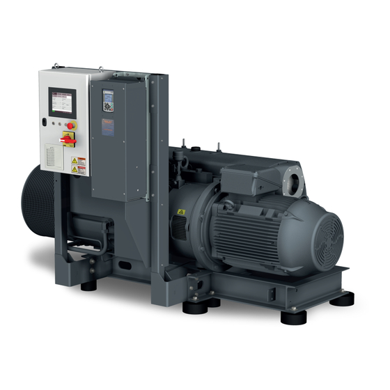
Product Description | 2 Product Description OUT1 PSA1 OUT2 PSA2 Air-oil heat exchanger Alarm indicator light Control unit Eye bolt Exhaust filter Emergency stop switch Filter material Float Valve Gas ballast valve User interface (human-machine) Suction connection LAN Communication port (Modbus TCP/IP) Level switch (oil level) Motor (pump drive) Main switch... -
Page 6: Operating Principle
Conveying of other media leads to an increased thermal and/or mechanical load on the machine and is permissible only after a consultation with Busch. The machine is intended for the placement in a non-potentially explosive environment. The machine is designed for indoor installation, in case of outdoor installation, ask your Busch representative in order to take specific precautions. -
Page 7: Standard Features
• Refer to the specific document “Pump Control Instructions, art. no.: 0870213261” for more details or contact your Busch representative. 2.3.5 Gas Ballast Valve The gas ballast valve mixes the process gas with a limited quantity of ambient air to counteract the condensation of vapour inside the machine. -
Page 8: Water-Oil Heat Recovery Unit
2 | Product Description 2.4.3 Water-Oil Heat Recovery Unit For heat recovery purpose or in case of unfavorable ambient conditions, a water-oil heat exchanger can be provided. See Cooling Water Connection (Optional) [► 20]. 2.5 P&ID "Piping and Instrumentation Diagram" DN150 PSA1 inlet gas MOT1... -
Page 9: Description Of User Interface Functions
Product Description | 2 2.7 Description of User Interface Functions The display is divided into three distinct parts. Menu tabs Information panel Bottom bar 01.08.2020 - 15:00 2.7.1 Menu Overview The menu consists of four main tabs with their own sub-tabs: –... -
Page 10: Bottom Bar
2 | Product Description 2.7.2 Bottom Bar The bottom bar provides different pieces of information, in particular the machine state and warning/alarm status. Warnings and alarms Date and hour Help Machine state status 01.08.2020 - 15:00 Screen WARNING brightness RUNNING ALARM 2.7.3 Navigation When several screens are available in the information panel, dots and “PREVIOUS/... -
Page 11: Role And User
– set the remote control and monitoring parameters, refer to the specific document "Pump Control Instructions, art. no.: 0870213261". – Role 3 ► Busch Service Only authorized personnel from Busch Service have this level of access rights. NOTE In case of any questions related to the machine settings: •... -
Page 12: System Settings
Warnings and Alarms Thresholds [► 47]. NOTE Advanced settings Advanced settings can only be changed by Busch Service “Role 3”, refer to the specific document "Pump Control Instructions, art. no.: 0870213261". 12 / 68 Instruction Manual R5 RA 1000-1600 A PLUS_EN_en... -
Page 13: Machine And Software Identification
HOME OPERATIONS SETTINGS CONTACT MODEL ETHERNET Vacuum pump type Vacuum pump model R5 PLUS RA 1600 A PLUS Software HMI Software PLC Serial number CHM120400012 2.7.7 Ethernet Settings To configure the ethernet settings according to your network: • Go to “SYSTEM” > “ETHERNET”. -
Page 14: Web Visualization
2 | Product Description SYSTEM HOME MAINTENANCE OPERATIONS SETTINGS MODEL ETHERNET CONTACT Ethernet settings Change settings Current IP address New IP address 192 . 168 . Current subnet mask New subnet mask 255 . 255 . 255 . Current gateway New gateway 192 . - Page 15 Product Description | 2 • Open your web browser (full screen window) and type the IP address of the machine to monitor in the address bar, followed by: :8080/smartpump.htm. By default, the whole address to be typed in the web browser is: 192.168.0.22:8080/smartpump.htm •...
- Page 16 2 | Product Description • The second page “Service” shows the service table of the machine and Busch service contact information. • The third page “My vacuum pump” gives general information about the machine. NOTE • Contact Busch: ð If the Ethernet port of the machine (COM) is already used for remote control / monitoring purpose.
-
Page 17: Transport
Transport | 3 Transport WARNING Suspended load. Risk of severe injury! • Do not walk, stand or work under suspended loads. WARNING Transport and lifting. Risk of severe injury! • Lift the machine from underneath with care to prevent the load from tipping over. •... -
Page 18: Storage
4 | Storage Storage • Seal all apertures with adhesive tape or reuse provided caps. NOTICE Long storage time. Risk of damage to the machine! • Due to a long storage time the capacitors of the variable-frequency drive can lose effi- ciency because of electrochemical processes. -
Page 19: Connecting Lines / Pipes
– DN150 PN16, EN 1092-1 If the machine is used as part of a vacuum system: • Busch recommends the installation of an isolation valve in order to prevent the oil from flowing back to the vacuum system. Instruction Manual R5 RA 1000-1600 A PLUS_EN_en... -
Page 20: Discharge Connection
5 | Installation 5.2.2 Discharge Connection CAUTION The discharge gas contains small quantities of oil. Risk to health! If air is discharged into rooms where persons are present: • Make sure that sufficient ventilation is provided. Connection size(s): – DN125 PN16, EN 1092-1 •... -
Page 21: Inlet Filter Condition Monitoring Kit
Installation | 5 – 19 mm hose (CWI / CWO) • In case of retrofit of a Water-oil Heat recovery unit: – Electrically connect the solenoid valve (MV) to the control unit (CU): connection ter- minals X1-5, X1-0V and X1-PE (see wiring diagram T511232067 in the control unit cabinet). -
Page 22: External Inlet Pressure Sensor
5 | Installation – Mechanically fit the pressure sensor on the body of the inlet filter. – Electrically connect the Inlet filter condition monitoring kit to the control unit (CU): connection terminals X1-24V and X1-34 (see wiring diagram T511232067 in the control unit cabinet). -
Page 23: Filling Oil
(mineral or synthetic) written on the nameplate (NP). In case of oil type change: • Contact your Busch representative to adapt the thresholds and service intervals ac- cordingly. For oil type and oil capacity see Technical Data [► 62] and Oil [► 63]. -
Page 24: Fitting The Coupling
5 | Installation 5.4 Fitting the Coupling Coupling hub (machine side) Coupling sleeve Coupling hub (motor side) Radial screw Max. admissible torque: 17 Nm Machine type Coupling size Value “E” (mm) Value “L” (mm) RA 1000 A PLUS ® BoWex I-80 RA 1600 A PLUS In case of a machine delivery without motor:... -
Page 25: Plus Machine
• If the machine is equipped with a power connector, install a residual current protective device to protect persons in case of isolation default. • Busch recommends installing a type B residual protective device and adapted to the electrical installation. -
Page 26: Wiring Diagram Control Unit
5 | Installation NOTICE Incorrect connection. Risk of damage to the control unit! • The wiring diagrams given below are typical. Check the inside of the control unit for connection instructions/diagrams. 5.5.2 Wiring Diagram Control Unit Internal view of the control unit: PLC1 XS 12 L1 L2 L3... -
Page 27: Commissioning
– Optional Inlet Valve Control [► 36], – Optional Vacuum Booster Control [► 37]. Do not hesitate to contact Busch to get any further information about the configuration of your machine. • Click on the “Help” icon in the bottom bar to get the contact information of your Busch representative, see Bottom Bar [► 10]. -
Page 28: In Operation
7 | In Operation CAUTION Noise of running machine. Risk of damage to hearing! If persons are present in the vicinity of a non noise insulated machine over extended pe- riods: • Make sure that ear protection is being used. To start the machine: •... -
Page 29: Control Mode
In Operation | 7 7.1 Control Mode To access the control mode menu: • Go to “OPERATIONS” > “MODE”. • Access to the third screen. HOME OPERATIONS MAINTENANCE SYSTEM WEEK PLANNER MODE PARAMETERS Control mode Local Manual Auto Start / Stop Digital speed control Remote Analog speed control... - Page 30 7 | In Operation HOME OPERATIONS MAINTENANCE SYSTEM WEEK PLANNER MODE PARAMETERS Start at Stop at Monday Tuesday Wednesday Thursday ↴ Friday ↳ Saturday Sunday As soon as the schedule is filled in, the control mode “Local/Auto” has to be activated (by “Role 2”...
-
Page 31: Remote/Auto
Remote Analog speed control Modbus control • Refer to the specific document “Pump Control Instructions, art. no.: 0870213261” for more details or contact your Busch representative. WARNING The machine may start without notice. Risk of severe injury! As soon as the “Remote” mode is activated: •... -
Page 32: Speed Control
• For smooth process pressure control, it is required to adjust the PID parameters. • Refer to the specific document “Pump Control Instructions, art. no.: 0870213261” for more details or contact your Busch representative. 32 / 68 Instruction Manual R5 RA 1000-1600 A PLUS_EN_en... -
Page 33: Ecomode
In Operation | 7 NOTE Display of the ultimate pressure. Due to sensor accuracy, the minimum displayed value of the ultimate pressure is 5 mbar preceded by the symbol "<", which means that the actual value is lower than dis- played. -
Page 34: Gas Ballast Valve Control
7 | In Operation 7.4 Gas Ballast Valve Control The gas ballast valve can be controlled (open/closed position) via a simple switch button. This operation is only available for “Role 2” users. To change the state of the gas ballast valve: •... -
Page 35: Conveying Condensable Vapours
7.5.1 Conveying Condensable Vapours Water vapour within the gas flow is tolerated within certain limits. The conveyance of other vapours shall be agreed upon with Busch. If condensable vapours are to be conveyed: Instruction Manual R5 RA 1000-1600 A PLUS_EN_en... -
Page 36: Optional Inlet Valve Control
7 | In Operation 70° C or • Open the isolation 30 minutes • Warm up the machine • Close the isolation START valve and perform the valve* (WARM-UP MODE) process • Cool-down the 30 minutes • Close the isolation machine valve (COOL-DOWN MODE) -
Page 37: Optional Vacuum Booster Control
In Operation | 7 10 s • Open the inlet valve* START and perform the process * not included in the scope of delivery The isolation valve control signal must be physically connected to the vacuum pump's control cabinet for the control to operate (see pump wiring diagram T511232067 in the control unit cabinet). - Page 38 7 | In Operation SYSTEM HOME MAINTENANCE OPERATIONS PARAMETERS WEEK PLANNER MODE Optional inlet valve control Opening delay after pump start-up Open / Closed Optional vacuum booster control Start pressure On / Off 20 mbar PREVIOUS The booster start signal is given by the PLUS pump when the pressure reaches a set val- ue (default value 20 mbar).
- Page 39 NOTICE Vacuum booster compatibility. Risk of damage to the machine! • Contact Busch to check the compatibility of the vacuum booster with the vacuum pump and the recommended starting pressure. Instruction Manual R5 RA 1000-1600 A PLUS_EN_en 39 / 68...
-
Page 40: Monitoring
7 | In Operation 7.8 Monitoring 7.8.1 Operating Information This display “HOME” > “MAIN” corresponds to the principal menu and is automatically loaded when the machine is started. It displays the principal operating information. HOME MAINTENANCE SYSTEM OPERATIONS ALARM MAIN MONITORING Inlet pressure Actual speed... -
Page 41: Operating Data
In Operation | 7 7.8.2 Operating Data This display “HOME” > “MONITORING” displays operating values, it is divided into three different screens. Screen 1 HOME OPERATIONS MAINTENANCE SYSTEM ALARM MAIN MONITORING > Gas-ballast valve Exhaust pressure Open 960 mbar Instant absorbed power Mean absorbed power 11.5 kW 10.2 kW... - Page 42 7 | In Operation Screen 2 HOME OPERATIONS MAINTENANCE SYSTEM ALARM MAIN MONITORING Oil temperature Exhaust gas temperature 82 °C Oil level PREVIOUS NEXT Oil temperature: Indicates the oil temperature, in case of a too high temperature a warn- ing or an alarm occurs, see Dysfunction [► 47]. Exhaust gas temperature: Indicates the exhaust gas temperature, in case of a too high temperature a warning or an alarm occurs, see Dysfunction [► 47].
- Page 43 In Operation | 7 Screen 3 HOME OPERATIONS MAINTENANCE SYSTEM MAIN MONITORING ALARM Energy consumption since last reset Reset energy consumption (Press button 5s) 921 kWh Energy consumption total Motor start counter, press 5s to reset 5412 kWh Inlet filter pressure differential = 1 mbar PREVIOUS NEXT...
-
Page 44: History
7 | In Operation 7.8.3 History This display “MAINTENANCE” > “HISTORY” shows the history of: – Events ► Parameter changes, function activation, etc… – Alarms ► Alarm signals from sensors – Warnings ► Warning signals from sensors – Service ► Service tasks completed It is possible to filter the type of message by selecting a specific tab. -
Page 45: Operating Curves
In Operation | 7 7.8.4 Operating Curves This display “MAINTENANCE” > “TREND” shows the trend curve of certain operating values. It offers the possibility to change the time lapse and the curve of 4 different operating values or all at the same time. MAINTENANCE SYSTEM HOME... - Page 46 7 | In Operation MAINTENANCE SYSTEM HOME OPERATIONS HISTORY SERVICE TREND Power consumption Oil temperature Inlet pressure Exhaust pressure 1500 1200 <=> 10kW 1000 1000 <=> 100°C 1000 <=> 1000mbar 1000 <=> 1000mbar g -45min -30min -15min 16:12:24 Select curve 46 / 68 Instruction Manual R5 RA 1000-1600 A PLUS_EN_en...
-
Page 47: Dysfunction
In Operation | 7 7.9 Dysfunction 7.9.1 Warnings and Alarms Thresholds When the machine has reached the limit threshold of an operating value, which is prede- fined in the system, a signal is sent and visible in the bottom bar. There are two signal levels: –... -
Page 48: Warning/Alarm Acknowledgment Procedure
NOTE Threshold values are preset with the factory settings. However, depending on the appli- cation, it is possible to adjust the threshold values only after Busch approval. Threshold changes are only available for "Role 3" users. 7.9.2 Warning/Alarm Acknowledgment Procedure... -
Page 49: Stop The Machine
When the warning/alarm message is no longer active the machine is ready to be restart- However, if the message remains, that means the problem is still pending. In this case, go back to the Troubleshooting [► 58] or ask your Busch representative for help. • Press on the Stop/Start button (SSB) to restart the machine. -
Page 50: Maintenance Schedule
Failing to properly maintain the machine. Risk of injuries! Risk of premature failure and loss of efficiency! • Respect the maintenance intervals or ask your Busch representative for service. 8.1 Maintenance Schedule The maintenance intervals depend very much on the individual operating conditions. The intervals given below are considered as starting values which should be shortened or ex- tended as appropriate. - Page 51 Maintenance | 8 • Check when the maintenance tasks have to be performed and how long the machine has operated since the first commissioning or last maintenance task. MAINTENANCE SYSTEM HOME OPERATIONS TREND HISTORY SERVICE Next exhaust filters service Exhaust filters service interval 3993 h 4000 h Reset...
-
Page 52: Oil Level Inspection
(mineral or synthetic) written on the nameplate (NP). In case of oil type change: • Contact your Busch representative to adapt the thresholds and service intervals ac- cordingly. 52 / 68 Instruction Manual R5 RA 1000-1600 A PLUS_EN_en... - Page 53 Maintenance | 8 1x seal, part no.: 0482 509 012 Drain pan Busch genuine spare parts 2x oil filter (OF), part no.: 0531 000 005 Oil filter wrench Instruction Manual R5 RA 1000-1600 A PLUS_EN_en 53 / 68...
-
Page 54: Exhaust Filter Change
8 | Maintenance For oil type and oil capacity see Technical Data [► 62] and Oil [► 63]. Check oil level 8.4 Exhaust Filter Change 6 mm hex key 16x (2x8) exhaust filter (EF) extract filter material (FM) 54 / 68 Instruction Manual R5 RA 1000-1600 A PLUS_EN_en... -
Page 55: Air Heat Exchanger Cleaning
Maintenance | 8 Filter material (FM) 1x part no.: 0537 000 042 1x part no.: 0537 000 043 Busch genuine spare parts, 16x (2x8) exhaust filter (EF), part no.: 0532 140 160 2x flat gasket 6 mm hex key part no.: 0480 000 131 Max. -
Page 56: Overhaul
• Decontaminate the machine as much as possible and state the contamination sta- tus in a ‘Declaration of Contamination’. Busch will only accept machines that come with a completely filled in and legally binding signed ‘Declaration of Contamination’ (form downloadable from www.buschvacuum.com). -
Page 57: Spare Parts
Use of non-Busch genuine spare parts. Risk of premature failure! Loss of efficiency! • The exclusive use of Busch genuine spare parts and consumables is recommended for the correct functioning of the machine and to validate the warranty. Spare parts kit Description Part no. -
Page 58: Troubleshooting
12 | Troubleshooting 12 Troubleshooting DANGER Carry out any work on the control unit and motor. Risk of electrical shock! • Electrical installation work must only be executed by qualified personnel. CAUTION Hot surface. Risk of burns! • Prior to any action requiring touching the machine, let the machine cool down first. NOTICE Variable-frequency drive maintenance. - Page 59 The inlet filter cartridge (IF) • Replace the inlet filter car- is partially clogged. tridge (IF). Internal parts are worn or • Repair the machine (con- damaged. tact Busch). The machine runs very Worn coupling (CPL). • Replace the coupling noisily. (CPL). Stuck vanes.
- Page 60 (pressure dersized for the application. work. control mode only). Leaks or pressure drops in • Ask Busch for advice. the pipework upstream the suction connection. Communication problems A wire is broken or not con- • Check the wiring between when the machine is nected.
- Page 61 Warning/ Alarm Acknowledgment Procedure [► 48]. Low battery The PLC battery is low. • Replace the PLC battery (alarm) (contact Busch). Fan breaker The circuit breaker of the • Refer to schematic and (alarm) cooling fan has tripped. reset the breaker.
-
Page 62: Technical Data
13 | Technical Data 13 Technical Data RA 1000 A PLUS RA 1600 A PLUS Nominal pumping speed m³/h 480 / 1200 600 / 1800 Ultimate pressure hPa (mbar) abs. 0.3 ... 0.5 ► see nameplate (NP) (without gas ballast valve) Ultimate pressure hPa (mbar) abs. -
Page 63: Oil
NOTE Mineral oil available only with water-cooling for RA 1600 A PLUS. In case of unfavourable ambient temperature, other oil viscosities may be used. Please consult your Busch repre- sentative for more details. To know which oil has been filled in the machine, please refer to the nameplate (NP). -
Page 64: Eu Declaration Of Conformity
This Declaration of Conformity and the CE-mark affixed to the nameplate are valid for the machine within the Busch scope of delivery. This Declaration of Conformity is issued under the sole responsibility of the manufacturer. When this machine is integrated into a superordinate machinery the manufacturer of the superordinate machinery (this can be the operating company, too) must conduct the conformity assessment process for the superordinate machine or plant, issue the Declaration of Conformity for it and affix the CE-mark. -
Page 65: Declaration Of Conformity
This Declaration of Conformity and the UKCA-mark affixed to the nameplate are valid for the machine within the Busch scope of delivery. This Declaration of Conformity is issued under the sole responsibility of the manufacturer. When this machine is integrated into a superordinate machinery the manufacturer of the superordinate machinery (this can be the operating company, too) must conduct the conformity assessment process for the superordinate machine or plant, issue the Declaration of Conformity for it and affix the UKCA-mark. - Page 66 Note...
- Page 67 Note...
- Page 68 Busch Vacuum Solutions We shape vacuum for you. Argentina Denmark Malaysia South Africa info@busch.com.ar info@busch.dk busch@busch.com.my info@busch.co.za Australia Finland Mexico Spain sales@busch.com.au info@busch.fi info@busch.com.mx contacto@buschiberica.es Austria France Netherlands Sweden busch@busch.at busch@busch.fr info@busch.nl info@busch.se Bangladesh Germany New Zealand Switzerland sales@busch.com.bd info@busch.de sales@busch.co.nz...
Need help?
Do you have a question about the R5 PLUS and is the answer not in the manual?
Questions and answers