BUSCH COBRA PLUS Instruction Manual
Dry screw vacuum pumps
Hide thumbs
Also See for COBRA PLUS:
- Instructions manual (40 pages) ,
- Instruction manual (80 pages) ,
- Instruction manual (68 pages)

Related Manuals for BUSCH COBRA PLUS


Summary of Contents for BUSCH COBRA PLUS
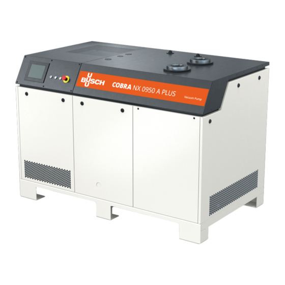
- Page 1 COBRA PLUS Dry Screw Vacuum Pumps NX 0950 A PLUS Instruction Manual 0870232499 | -0002_en-US | Original instructions 3/21/2023...
-
Page 2: Table Of Contents
Table of Contents Table of Contents Safety ..................................Product Description ............................. Operating Principle ............................. Intended Use ............................... Standard Features............................... 2.3.1 User Interface ............................2.3.2 Acoustic Cabinet ........................... 2.3.3 Control Unit ............................2.3.4 Monitoring Devices ..........................2.3.5 I/O and Communication Port......................2.3.6 Gas Ballast Valve........................... - Page 3 Table of Contents Control Mode ............................... 8.1.1 Local/Manual............................8.1.2 Local/Auto "Week Planner" ......................... 8.1.3 Remote/Auto ............................Operating Mode ..............................8.2.1 Speed Control ............................8.2.2 Pressure Control........................... Ecomode................................Warm-up / Cool-down Modes..........................8.4.1 Conveying Condensable Vapors......................Inlet Valve Control............................... Vacuum Booster Control ............................ Monitoring ................................
-
Page 4: Safety
Safety Prior to handling the machine, this instruction manual should be read and understood. If anything needs to be clarified, please contact your Busch representative. Read this manual carefully before use and keep for future reference. This instruction manual remains valid as long as the customer does not change anything on the product. -
Page 5: Product Description
Product Description | 2 Product Description Description Suction connection (Inlet) Discharge connection (Outlet) Acoustic cabinet Alarm indicator light Barrier gas connection Cooling air inlet Cooling air outlet Condensate drain Cooling fan Control unit Cooling water inlet Cooling water outlet Emergency stop switch User interface (Human-Machine) Communication port (Modbus TCP/IP) Nameplate... - Page 6 2 | Product Description Vacuum pump (VP) PSA1 PSA2 Description Suction connection (Inlet) Discharge connection (Outlet) Barrier gas connection Barrier gas flow meter Barrier gas manometer Barrier gas pressure regulator Solenoid valve (Barrier gas) Condensate drain Cooling water drain plug Cooling water inlet Cooling water outlet Eye bolt...
-
Page 7: Operating Principle
Product Description | 2 Description Resistance thermometer (Pump tempera- Waterflow sensor (Cooling liquid) ture) Solenoid valve (Cooling water) NOTE Technical term. In this instruction manual, we consider that the term ‘machine’ refers to the ‘vacuum pump’. NOTE Illustrations In this instruction manual, the illustrations may differ from the machine appearance. NOTE Illustrations and displays of the Human-Machine Interface (HMI). -
Page 8: Intended Use
Conveying of other media leads to an increased thermal and/or mechanical load on the machine and is permissible only after a consultation with Busch. The machine is intended for indoor placement in a non-potentially explosive environment. The machine is capable of maintaining ultimate pressure, see Technical Data. -
Page 9: Monitoring Devices
The control unit (CU) is equipped with a RJ45 (Modbus) communication port that can allow remote control and monitoring of the machine. ● Refer to the specific document “Pump Control Instructions, art. no.: 0870213261” for more details or contact your Busch representative. 2.3.6 Gas Ballast Valve The gas ballast valve mixes the process gas with a limited quantity of ambient air to counteract the condensation of vapor inside the machine. -
Page 10: Silencer
2 | Product Description Depending on the application, the sealing systems efficiency can be improved with a barrier gas sys- tem, see Barrier Gas System [➔ 10]. 2.3.10 Silencer The silencer reduces the exhaust gas noise at the machine discharge (OUT). 2.3.11 Barrier Gas System The barrier gas system allows the supply of compressed air or nitrogen into the motor side shaft... -
Page 11: Led Indicators
Product Description | 2 Description Non-return valve (Not used as an isolation PSA1 Pressure transmitter (Inlet gas pressure) valve) PSA2 Pressure transmitter (Exhaust gas pressure Resistance thermometer (Pump safety tem- before silencer) perature) Vacuum pump Water flow sensor (Cooling liquid) Solenoid valve (Cooling water) LED Indicators Next to the user interface, there are three LEDs giving a visual indication of the state of machine. -
Page 12: Menu Overview
2 | Product Description 2.6.1 Menu Overview The menu consists of four main tabs with their own sub-tabs: ● The "HOME" tab is the main display and is mainly useful for live monitoring. ● The “OPERATIONS” tab displays the operating parameters/modes and allows the control of the machine. -
Page 13: Navigation
Product Description | 2 2.6.3 Navigation When several screens/pages are available in the information panel, dots representing the different screens/pages and “PREVIOUS/NEXT” buttons are displayed above the bottom bar. ● Press either on a dot or “PREVIOUS/NEXT” button to pass from a screen/page to another. The switch button is black when deactivated and orange when activated. - Page 14 ● set the remote control and monitoring parameters, refer to the specific document "Pump Con- trol Instructions, art. no.: 0870213261". Role 3 ► Busch Service Only authorized personnel from Busch Service have this level of access rights. NOTE In case of any questions related to the machine settings: ●...
-
Page 15: System Settings
Warnings and Alarms Thresholds [➔ 57]. NOTE Advanced settings Advanced settings can only be changed by Busch Service “Role 3”, refer to the specific docu- ment "Pump Control Instructions, art. no.: 0870213261". Instruction Manual COBRA NX 0950 A PLUS_EN_en... -
Page 16: Machine And Software Identification
2 | Product Description 2.6.6 Machine and Software Identification To display the machine and software identification: ● Go to “SYSTEM” > “MODEL”. 2.6.7 Ethernet Settings ● To configure the ethernet settings according to your network: ● Go to “SYSTEM” > “ETHERNET”. ●... -
Page 17: Web Visualization
Product Description | 2 Description Default value IP address 192.168.0.22 Subnet mask 255.255.255.0 Gateway 192.168.0.1 PLC port (0-65535) 502 (cannot be changed) PLC Slave no. 247 (F7) (cannot be changed) Web Visualization Each machine has a built-in Web visualization interface, which allows remote monitoring of the main operating parameters from a computer (via a LAN connection or via an optional WIFI connection), a tablet or a smartphone (via an optional WIFI connection). - Page 18 (machine status, operating mode, running hours, inlet pressure…). ● Use the icons in the bottom bar to navigate in the Web visualization interface. ● The second page “Service” shows the service table of the machine and Busch service contact in- formation.
- Page 19 Product Description | 2 ● The third page “My vacuum pump” gives general information about the machine. ● The fourth page "Operations" gives remote access to the basic settings of the vacuum pump: Control mode, Operating mode, Ecomode, Week planner, Warm-up and Cool-down, Inlet valve control, Vacuum booster control.
- Page 20 NOTE Remote start/stop. Remote start/stop of the vacuum pump is not possible via the Web Visualization interface. NOTE ● Contact Busch: If the Ethernet port of the machine (COM) is already used for remote control / monitoring ➔ purpose. In order to use the Web visualization function via a WIFI connection (requires an optional ➔...
-
Page 21: Transport
Transport | 3 Transport WARNING Suspended load. Risk of severe injury! ● Do not walk, stand or work under suspended loads. WARNING Transport and lifting. Risk of severe injury! ● Lift the machine from underneath with care to prevent the load from tipping over. ●... - Page 22 3 | Transport As soon as the machine is placed at its final location: ● Remove the reinforcement bar as it can hinder a technician when performing maintenance tasks. ● Conserve and remount it for future machine transport. Description Remove side cover (Quarter turn key delivered loose) ●...
-
Page 23: Storage
Storage | 4 Storage ● Seal all apertures with adhesive tape or reuse provided caps. NOTICE Long storage time. Risk of damage to the machine! ● Due to a long storage time the capacitors of the variable speed drive can lose efficiency because of electrochemical processes. -
Page 24: Installation
5 | Installation Installation Installation Conditions NOTICE Use of the machine outside of the permitted installation conditions. Risk of premature failure! Loss of efficiency! ● Take care that the installation conditions are fully complied with. Description ~50 cm ~100 cm ~100 cm ~100 cm ~5 cm... -
Page 25: Connecting Lines / Pipes
● Make sure that the cooling water complies with the requirements, see Cooling Water Connection [➔ 27]. If the machine is installed at an altitude greater than 1000 meters above sea level: ● Contact your Busch representative, the ambient temperature should be limited. Connecting Lines / Pipes ● Remove all protective covers before installation. -
Page 26: Discharge Connection
5 | Installation 5.2.2 Discharge Connection NOTICE Discharge gas flow obstructed. Risk of damage to the machine! ● Make sure that the discharged gas will flow without obstruction. Do not shut off or throttle the discharge line or use it as a pressurized air source. Connection size(s): –... -
Page 27: Cooling Water Connection
Installation | 5 5.2.4 Cooling Water Connection Description Cooling water inlet Cooling water outlet ● Connect the cooling water connections (CWI / CWO) to the water supply. Connection size: – G1/2, ISO 228-1 (CWI / CWO) ● Make sure that the cooling water complies with the following requirements: Supply capacity l/min 8 ... 16... -
Page 28: Barrier Gas System Connection
5 | Installation 5.2.5 Barrier Gas System Connection Description Barrier gas connection Barrier gas solenoid valve Flow meter (BGF) Manometer (BGM) Pressure regulating valve (BGR) ● Connect the barrier gas connection (BGC) to the gas supply. Connection size: – G3/8, ISO 228-1 ●... -
Page 29: Filling Oil
Use of an inappropriate oil. Risk of premature failure! Loss of efficiency! ● Only use an oil type which has previously been approved and recommended by Busch. For oil type and oil capacity see Technical Data and Oil [➔ 82]. Description... - Page 30 __ / __ / ____ Oil type see nameplate Change interval see instruction manual If there is no sticker (part no. 0565 568 959) on the machine: ● Order it from your Busch representative. 30 | 88 Instruction Manual COBRA NX 0950 A PLUS_EN_en...
-
Page 31: Gas Ballast Opening And Closing
Installation | 5 Gas Ballast Opening and Closing Description Remove central back cover (Quarter Open position turn key delivered loose) Closed position Instruction Manual COBRA NX 0950 A PLUS_EN_en 31 | 88... -
Page 32: Electrical Connection
● Make sure that the motor of the machine will not be affected by electric or electromagnetic dis- turbance from the mains, if necessary seek advice from Busch. ● Make sure that the EMC of the machine is compliant with the requirements of your supply net- work system, if necessary provide further interference suppression (EMC of the machine, see EU Declaration of Conformity [➔ 83] or UK Declaration of Conformity [➔ 84]). - Page 33 ● If the machine is equipped with a power connector, install a residual current protective device to protect persons in case of a defective insulation. ● Busch recommends installing a type B residual protective device suitable for the electrical in- stallation.
-
Page 34: Wiring Diagram Control Unit
6 | Electrical Connection Description Remove left front cover (Quarter turn Open control unit (CU) key delivered loose) Wiring Diagram Control Unit Internal view of the control unit Description Power input Box fan VSD: Variable Speed Drive Filter on EMC filter Box filter 34 | 88 Instruction Manual COBRA NX 0950 A PLUS_EN_en... - Page 35 Electrical Connection | 6 Customer power supply Description Power supply Standard Control Unit: Power supply Optional Control Unit: 3L+PE 380-440V +/-10% (50/60Hz) 3L+PE 380-460V +/-10% (50/60Hz) Wire gauge according to EN 60204-1 Must be provided by the customer Lockable disconnect switch Overload protection: C-curve - 80A without DCR / C-curve - 50A with DCR Vacuum pump terminal board (L1, L2,...
-
Page 36: Commissioning
7 | Commissioning Commissioning Prerequisites Before Use NOTICE The machine can be shipped without oil. Operation without oil will ruin the machine in short time! ● Prior to commissioning, the machine must be filled with oil, see Filling Oil [➔ 29]. ●... -
Page 37: Configuration
Do not hesitate to contact Busch to get any further information about the configuration of your ma- chine. ● Click on the “Help” icon in the bottom bar to get the contact information of your Busch represen- tative, see Bottom Bar [➔ 12]. -
Page 38: Start Up
7 | Commissioning Start Up NOTICE The machine can be shipped without oil. Operation without oil will ruin the machine in short time! ● Prior to commissioning, the machine must be filled with oil, see Filling Oil [➔ 29]. NOTICE Lubricating a dry running machine (compression chamber). Risk of damage to the machine! ●... - Page 39 Commissioning | 7 As soon as a warning/alarm signal occurred: ● Investigate the cause of the signal, see Dysfunction [➔ 57]. NOTE Activated oil level signal. The machine is generally shipped without oil, therefore an alarm signal occurs during the first start-up.
-
Page 40: In Operation
8 | In Operation In Operation CAUTION During operation the surface of the suction and exhaust connections may reach temperatures of more than 70°C. Risk of burns! ● Avoid contact with these surfaces during and directly after operation. CAUTION Remove covers during operation. Risk of burns! ●... -
Page 41: Local/Manual
In Operation | 8 8.1.1 Local/Manual Configured by default, this mode allows to control manually the machine directly from the user in- terface (HMI). 8.1.2 Local/Auto "Week Planner" The "week planner" function allows definition of a weekly schedule for starting or stopping the ma- chine automatically using the current local settings. -
Page 42: Remote/Auto
8 | In Operation WARNING The machine may start without notice. Risk of severe injury! As soon as the mode “Local/Auto” is activated: ● Make sure the machine is fully operational when the programmed schedule begins. NOTE To allow the machine to operate non-stop from one day to the next one, select 23:59 as the stop time on the first day and 00:00 as the start time on the second day. -
Page 43: Operating Mode
In Operation | 8 ● Refer to the specific document “Pump Control Instructions, art. no.: 0870213261” for more details or contact your Busch representative. WARNING The machine may start without notice. Risk of severe injury! As soon as the “Remote” mode is activated: ●... -
Page 44: Pressure Control
● For smooth process pressure control, it is required to adjust the PID parameters. ● Refer to the specific document “Pump Control Instructions, art. no.: 0870213261” for more details or contact your Busch representative. NOTE Display of the ultimate pressure. -
Page 45: Ecomode
In Operation | 8 Ecomode The Ecomode stops the machine when the inlet pressure has reached the preset "ecomode pres- sure" within a defined time delay and will restart once the inlet pressure exceeds the "restart pres- sure". This mode is only available for “Role 2” users, see Roles and Users [➔ 13]. ●... -
Page 46: Warm-Up / Cool-Down Modes
8 | In Operation Warm-up / Cool-down Modes The warm-up mode allows the machine to obtain a suitable operating temperature for the process. The cool-down mode allows the evacuation of any condensable vapors, refer to chapter Conveying Condensable Vapours for conditions to be met. During these phases, the machine operates at maximum speed, recommended with the gas ballast valve open to warm up and evacuate a maximum of humidity. -
Page 47: Conveying Condensable Vapors
● Make sure that the condensate drain (CD) is open. ● Water vapor within the gas flow is tolerated within certain limits. The conveyance of other vapors shall be agreed upon with Busch. Instruction Manual COBRA NX 0950 A PLUS_EN_en... -
Page 48: Inlet Valve Control
8 | In Operation Inlet Valve Control This menu allows the control and setting of the opening parameters of an inlet valve installed at the suction side of the vacuum pump (not included in the scope of delivery of the vacuum pump). This parameter is only available for “Role 2”... - Page 49 In Operation | 8 0VDC Inlet Valve Wiring Diagram Description PLUS Pump control unit Inlet Valve command line (24VDC from PLUS Pump - Max 1A) Customer side Power line from customer with appro- priate protection Customer Inlet valve Customer relay NOTE The installation of an isolation valve at the vacuum pump inlet also requires the installation of an external pressure sensor to control the vacuum pump, see External Inlet Pressure Sensor...
-
Page 50: Vacuum Booster Control
8 | In Operation Vacuum Booster Control This menu allows the control and setting of the start-up parameters of a vacuum booster installed at the suction side of the vacuum pump (not included in the scope of delivery of the vacuum pump). This parameter is only available for “Role 2”... - Page 51 NOTICE Vacuum booster compatibility. Risk of damage to the machine! ● Contact Busch to check the compatibility of the vacuum booster with the vacuum pump and the recommended starting pressure. Instruction Manual COBRA NX 0950 A PLUS_EN_en 51 | 88...
-
Page 52: Monitoring
8 | In Operation Monitoring 8.7.1 Operating Information This display “HOME” > “MAIN” corresponds to the principal menu and is automatically loaded when the machine is started. It displays the principal operating information. Inlet pressure: Indicates the operating pressure at the suction connection (IN) according to the se- lected unit. -
Page 53: Operating Data
In Operation | 8 8.7.2 Operating Data This display “HOME” > “MONITORING” displays operating values, it is divided into three different screens/pages. Screen/Page 1 Barrier gas solenoid valve: Indicates the state of the barrier gas solenoid valve ► “Open” or “Closed”. - Page 54 8 | In Operation Screen/Page 2 Pump temperature: Indicates the pump coolant temperature, in case of a too high temperature a warning or an alarm occurs, see Dysfunction [➔ 57]. Water flow: Indicates the cooling liquid water flow in the cooling liquid circuit in l/min. Oil level: Indicates the oil level state on the A side (motor side) and on the B side (suction side) ►...
-
Page 55: History
In Operation | 8 Reset energy consumption: Allows the resetting of the energy consumption reading by pressing the switch button for 5 seconds. Energy consumption total: Indicates the total energy consumption in kWh since the first machine commissioning. Motor start counter: Indicates the number of starts since the first machine commissioning. Inlet filter pressure differential: Indicates the pressure differential in the inlet filter cartridge (only if the inlet filter condition monitoring kit is installed). -
Page 56: Operating Curves
8 | In Operation 8.7.4 Operating Curves The “MAINTENANCE” > “TREND” display shows the trend curve of one or more operating values. It offers the possibility to change the time lapse and the curve of 5 different operating values or all at the same time. -
Page 57: Dysfunction
In Operation | 8 Dysfunction 8.8.1 Warnings and Alarms Thresholds When the machine has reached the limit threshold of an operating value, which is predefined in the system, a signal is sent and visible in the bottom bar. There are two signal levels: ●... - Page 58 >50°C for 60 seconds NOTE Threshold values are preset with the factory settings. However, depending on the application, it is possible to adjust the threshold values only after Busch approval. Threshold changes are only available for "Role 3" users. 58 | 88...
-
Page 59: Warning/Alarm Acknowledgment Procedure
When the warning/alarm message is no longer active the machine is ready to be restarted. Howev- er, if the message remains, this means that the problem is still pending. In this case, refer again to the Troubleshooting or ask your Busch representative for help. ● Press on the Stop/Start button (SSB) to restart the machine. -
Page 60: Stop The Machine
8 | In Operation Stop the Machine To stop the machine: ● Press and hold the start/stop button (SSB) for at least 3 seconds. In case of emergency stop: ● Push the emergency stop switch (ESS). As long as the power indicator light (PIL) is green, the machine is still powered. NOTE Control mode “Remote/Auto”. -
Page 61: Maintenance
Risk of premature failure and loss of efficiency! ● Maintenance work must only be executed by qualified personnel. ● Respect the maintenance intervals or ask your Busch representative for service. Instruction Manual COBRA NX 0950 A PLUS_EN_en 61 | 88... -
Page 62: Maintenance Schedule
Maintenance work Monthly ● Check the machine for oil leaks - in case of leaks have the machine repaired (contact Busch). Every 6 months ● Clean the machine from dust and dirt, especially the cool- ing air inlet and outlet (CAI/CAO), see Machine Cleaning [➔ 73]. - Page 63 (TSA). ● Clean the magnetic plugs (MP). Every 25000 hours or after 4 ● Have a major overhaul on the machine (contact Busch). years To visualize information about remaining hours: ● Go to “MAINTENANCE” > “SERVICE”.
-
Page 64: Oil Level Inspection
9 | Maintenance Oil Level Inspection If the oil level is too low, an alarm signal will be sent by the monitoring system. To check the oil level status: ● Go to “HOME” > “MONITORING”. ● In the cell “Oil level”, “OK” must always be written. To perform a visual control of the oil level: ●... -
Page 65: Cleaning The Inlet Screen
Maintenance | 9 NOTE Oil level and Oil level alarm. Risk of machine shutdown! ● When the oil level is in the lower half of the target of the oil sight glass, the machine may stop be- cause of the oil level alarm. Fill up as required. Cleaning the Inlet Screen Description Remove side cover (Quarter turn key... -
Page 66: Cleaning The Gas Ballast Filter
9 | Maintenance ● Prior to instruction 5, disconnect the pressure sensor. ● Once the inlet screen has been cleaned, put it back in place and reassemble the elements in re- verse order from 5 to 1. Cleaning the Gas Ballast Filter ●... -
Page 67: Cleaning The Silencer
Maintenance | 9 Description Remove the gas ballast filter with a 36 Use compressed air and wear protec- mm wrench tive eyewear and mask ● Once the cleaning is completed, reassemble the gas ballast filter, and open the gas ballast valve. Cleaning the Silencer Description Remove side cover (Quarter turn key... - Page 68 9 | Maintenance Description Remove the exhaust flange of the si- Tilt the silencer before removing it lencer* through the hole in the cabinet through the side of the cabinet cover NOTE *Removal of the exhaust flange. When removing the exhaust flange, the Teflon sealing tape will be deteriorated and no longer usable! ●...
- Page 69 Maintenance | 9 Description Wear protective eyewear and mask Use compressed air and cleaning clothes to clean the inside and outside of the silencer ● Once the inner parts of the silencer have been cleaned, reassemble them. ● Put the silencer back in place and reassemble the elements in reverse order from 5 to 1. Make sure to apply a new Teflon sealing tape before reassembling the exhaust flange.
-
Page 70: Oil Change
Use of an inappropriate oil. Risk of premature failure! Loss of efficiency! ● Only use an oil type which has previously been approved and recommended by Busch. Description At the motor side: Remove central back At the suction side: Remove side cover... - Page 71 Maintenance | 9 Description Oil draining at the motor side Magnetic plug Description Oil draining at the suction side Magnetic plug For oil type and oil capacity see Technical Data and Oil [➔ 82]. Instruction Manual COBRA NX 0950 A PLUS_EN_en 71 | 88...
- Page 72 9 | Maintenance Description Remove central back cover (Quarter turn key delivered loose) Description Remove side cover (Quarter turn key delivered loose) 72 | 88 Instruction Manual COBRA NX 0950 A PLUS_EN_en...
-
Page 73: Machine Cleaning
If there is no sticker (part no. 0565 568 959) on the machine: ● Order it from your Busch representative. Machine Cleaning ● Clean the cooling air inlet and outlet (CAI/CAO) with pressurized air, especially when the machine is in a dusty environment. -
Page 74: Overhaul
● Decontaminate the machine as much as possible and state the contamination status in a ‘Dec- laration of Contamination’. Busch will only accept machines that come with a completely filled in and legally binding signed ‘Declaration of Contamination’ (form downloadable from www.buschvacuum.com). -
Page 75: Decommissioning
Decommissioning | 11 Decommissioning DANGER Live wires. Risk of electrical shock. ● Electrical installation work must only be executed by qualified personnel. CAUTION Hot surface. Risk of burns! ● Prior to any action requiring touching the machine, let the machine cool down first. ●... -
Page 76: Spare Parts
Use of non-Busch genuine spare parts. Risk of premature failure! Loss of efficiency! ● The exclusive use of Busch genuine spare parts and consumables is recommended for the correct functioning of the machine and to validate the warranty. Spare parts available:... -
Page 77: Troubleshooting
Troubleshooting | 13 Troubleshooting DANGER Carry out any work on the control unit and motor. Risk of electrical shock! ● Electrical installation work must only be executed by qualified personnel. CAUTION Hot surface. Risk of burns! ● Prior to any action requiring touching the machine, let the machine cool down first. NOTICE Variable speed drive maintenance. - Page 78 The machine does not reach The machine is over or under- ● Check the system pipework. the target pressure (pressure sized for the application. ● Ask Busch for advice. control mode only). Leaks or pressure drops in the pipework upstream the suction connection.
- Page 79 Inverter (VSD) Variable Speed Drive (VSD) de- ● Have the variable speed (alarm) fault. drive checked by an electri- cian. ● Repair the variable speed drive (contact Busch). Instruction Manual COBRA NX 0950 A PLUS_EN_en 79 | 88...
- Page 80 ● Refer to schematic and re- nected connected or has been discon- connect the analog input nected. module. For resolution of problems not listed in the troubleshooting table, please contact your Busch repre- sentative. 80 | 88 Instruction Manual COBRA NX 0950 A PLUS_EN_en...
-
Page 81: Technical Data
Technical Data | 14 Technical Data NX 0950 A PLUS Pumping speed m³/h Ultimate pressure hPa (mbar) abs. ≤0.01 (without gas ballast) Ultimate pressure hPa (mbar) abs. ≤0.05 (with gas ballast) Nominal motor rating (72Hz) 18.5 Permitted motor speed range 1200 …... -
Page 82: Oil
15 | Oil VSC 100 ISO-VG Oil type Synthetic Part number 1 L packaging 0831 168 356 Part number 5 L packaging 0831 168 357 Part number 10 L packaging 0831 210 162 Part number 20 L packaging 0831 168 359 Oil suitability ● Oil VSC 100: Suitable for harsh applications. 82 | 88 Instruction Manual COBRA NX 0950 A PLUS_EN_en... -
Page 83: Eu Declaration Of Conformity
EU Declaration of Conformity This Declaration of Conformity and the CE-markings affixed to the nameplate are valid for the machine within the Busch scope of delivery. This Decla- ration of Conformity is issued under the sole responsibility of the manufacturer. -
Page 84: Uk Declaration Of Conformity
UK Declaration of Conformity This Declaration of Conformity and the UKCA-markings affixed to the nameplate are valid for the machine within the Busch scope of delivery. This Dec- laration of Conformity is issued under the sole responsibility of the manufacturer. - Page 85 N otes Notes Instruction Manual COBRA NX 0950 A PLUS_EN_en 85 | 88...
- Page 86 Notes 86 | 88 Instruction Manual COBRA NX 0950 A PLUS_EN_en...
- Page 87 Notes Instruction Manual COBRA NX 0950 A PLUS_EN_en 87 | 88...
- Page 88 With a network of over 60 companies in more than 40 countries and agencies worldwide, Busch has a global presence. In every country, highly competent local personnel delivers custom-tailored support backed by a global network of expertise. Wherever you are.
Need help?
Do you have a question about the COBRA PLUS and is the answer not in the manual?
Questions and answers