
Related Manuals for BUSCH R5 PLUS


Summary of Contents for BUSCH R5 PLUS
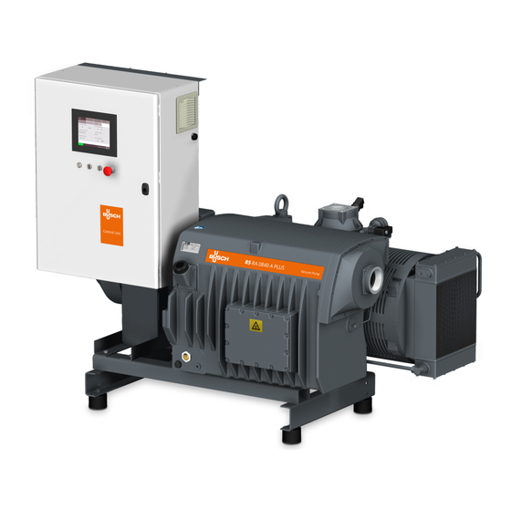
- Page 1 R5 PLUS Oil-Lubricated Rotary Vane Vacuum Pumps RA 0840 A PLUS without cabinet Instruction Manual 0870242418 | -0001_en-US | Original instructions 2/22/2023...
-
Page 2: Table Of Contents
Table of Contents Table of Contents Safety ..................................Product Description ............................. Operating Principle ............................. Intended Use ............................... Standard Features............................... 2.3.1 User Interface ............................2.3.2 Control Unit ............................2.3.3 Monitoring Devices ..........................2.3.4 I/O and Communication Port......................2.3.5 Gas Ballast Valve........................... Optional Accessories............................ - Page 3 Table of Contents Operating Mode ..............................8.2.1 Speed Control ............................8.2.2 Pressure Control........................... Ecomode................................Gas Ballast Valve Control ........................... Warm-up / Cool-down Modes..........................8.5.1 Conveying Condensable Vapors......................Optional Inlet Valve Control..........................Optional Vacuum Booster Control ........................Monitoring ................................8.8.1 Operating Information ........................8.8.2 Operating Data .............................
-
Page 4: Safety
Safety Prior to handling the machine, this instruction manual should be read and understood. If anything needs to be clarified, please contact your Busch representative. Read this manual carefully before use and keep for future reference. This instruction manual remains valid as long as the customer does not change anything on the product. -
Page 5: Product Description
Product Description | 2 Product Description PSA1 PSA2 Description Suction connection (Inlet) Discharge connection (Outlet) Air-oil heat exchanger Alarm indicator light Control unit Eye bolt Exhaust filter Emergency stop switch Filter material Gas ballast valve User interface (Human-Machine) LAN Communication port (Modbus TCP/IP) Level switch (Oil level) Motor (Pump drive) Nameplate... -
Page 6: Operating Principle
Busch. The machine is intended for the placement in a non-potentially explosive environment. The machine is designed for indoor installation, in case of outdoor installation, ask your Busch rep- resentative in order to take specific precautions. -
Page 7: Standard Features
The control unit (CU) is equipped with a RJ45 (Modbus) communication port that can allow remote control and monitoring of the machine. ● Refer to the specific document “Pump Control Instructions, art. no.: 0870213261” for more details or contact your Busch representative. 2.3.5 Gas Ballast Valve The gas ballast valve mixes the process gas with a limited quantity of ambient air to counteract the condensation of vapor inside the machine. -
Page 8: P&Id "Piping And Instrumentation Diagram
2 | Product Description P&ID "Piping and Instrumentation Diagram" Description Air-oil heat exchanger (Fan driven by the Coupling pump shaft) Gas ballast Inlet filter (Optional) Suction connection (Inlet) Level switch "alarm/trip” (Oil level) MOT1 Motor (Pump drive) Non-return valve (Not used as an isolation valve) Oil filter Discharge connection (Outlet) -
Page 9: Description Of User Interface Functions
Product Description | 2 Description Alarm indicator light (AIL): The LED flashes in red when a warning occurred. The LED is continuously red when an alarm occurred. Description of User Interface Functions The display is divided into three distinct parts. Description Menu tabs and sub-tabs Information panel... -
Page 10: Bottom Bar
2 | Product Description ● The “SYSTEM” tab allows to set or change settings and provides information about the product and its distributor. 2.7.2 Bottom Bar The bottom bar provides different pieces of information, in particular the machine state and warn- ing/alarm status. -
Page 11: Roles And Users
● set the remote control and monitoring parameters, refer to the specific document "Pump Con- trol Instructions, art. no.: 0870213261". Role 3 ► Busch Service Only authorized personnel from Busch Service have this level of access rights. NOTE In case of any questions related to the machine settings: ●... -
Page 12: System Settings
2 | Product Description ● Press on the three stars. ● Enter the correct password in the number pad according to your access right. ● Press “Save”. ● From now on, the specific rights are open for a limited period ► delay of 5 minutes. 2.7.5 System Settings ●... -
Page 13: Machine And Software Identification
Thresholds can only be changed by Busch Service “Role 3”, see the predefined factory settings in the chapter Warnings and Alarms Thresholds [➔ 51]. NOTE Advanced settings Advanced settings can only be changed by Busch Service “Role 3”, refer to the specific docu- ment "Pump Control Instructions, art. no.: 0870213261". 2.7.6 Machine and Software Identification To display the machine and software identification: ●... -
Page 14: Web Visualization
2 | Product Description NOTE The current Ethernet values are displayed in the left side of the screen (Ethernet settings). To change these values, it is necessary to fill in all the fields in the right side of the screen (Change settings) before applying the changes by pressing on the switch button: ●... - Page 15 Product Description | 2 ● Check the ethernet settings of the machine in the “Ethernet Settings” menu of the User Interface Display (HMI), see Ethernet Settings [➔ 13]. By default, the ethernet settings are: ● IP address: 192.168.0.22 ● Subnet mask: 255.255.255.0 ●...
- Page 16 2 | Product Description ● The second page “Service” shows the service table of the machine and Busch service contact in- formation. ● The third page “My vacuum pump” gives general information about the machine. ● The fourth page "Operations" gives remote access to the basic settings of the vacuum pump: Control mode, Operating mode, Ecomode, Week planner, Warm-up and Cool-down, Gas ballast valve control, Optional inlet valve control, Optional vacuum booster control.
- Page 17 NOTE Remote start/stop. Remote start/stop of the vacuum pump is not possible via the Web Visualization interface. NOTE ● Contact Busch: If the Ethernet port of the machine (COM) is already used for remote control / monitoring ➔ purpose. In order to use the Web visualization function via a WIFI connection (requires an optional ➔...
-
Page 18: Transport
3 | Transport Transport WARNING Suspended load. Risk of severe injury! ● Do not walk, stand or work under suspended loads. WARNING Lifting the machine using the motor eye bolt. Risk of severe injury! ● Do not lift the machine using the eye bolt fitted to the motor. Only lift the machine as shown. NOTICE In case the machine is already filled with oil. -
Page 19: Storage
Storage | 4 Storage ● Seal all apertures with adhesive tape or reuse provided caps. If the machine is to be stored for more than 3 months: ● Wrap the machine in a corrosion inhibiting film. ● Store the machine indoors, dry, dust free and if possible in original packaging preferably at temperatures between 0 ... -
Page 20: Installation
● Make sure that all provided covers, guards, hoods, etc. are mounted. If the machine is installed at an altitude greater than 1000 meters above sea level: ● Contact your Busch representative, the motor should be derated or the ambient temperature limited. -
Page 21: Connecting Lines / Pipes
– G3” If the machine is used as part of a vacuum system: ● Busch recommends the installation of an isolation valve in order to prevent the oil from flow- ing back to the vacuum system. Instruction Manual R5 RA 0840 A PLUS without cabinet_EN_en... -
Page 22: Discharge Connection
5 | Installation 5.2.2 Discharge Connection CAUTION The discharge gas contains small quantities of oil. Risk to health! If air is discharged into rooms where persons are present: ● Make sure that sufficient ventilation is provided. NOTICE Discharge gas flow obstructed. Risk of damage to the machine! ●... - Page 23 Installation | 5 The thermostatic valve (TV) is used to control the oil flow in order to keep a stable machine tempera- ture. The factory adjustment of the thermostatic valve (TV) is approx. 55°C-70°C oil temperature. The solenoid valve (MV) is used to stop the cooling water circulation when the machine is not run- ning or when the oil temperature is lower than 60°C.
-
Page 24: Inlet Filter Condition Monitoring Kit
5 | Installation 5.2.4 Inlet Filter Condition Monitoring Kit ● To install the Inlet filter condition monitoring kit: ● Remove the R1/4 screw plug from the inlet filter cover ● Mechanically fit the pressure sensor on the body of the inlet filter. ●... -
Page 25: Filling Oil
Use of an inappropriate oil. Risk of premature failure! Loss of efficiency! ● Only use an oil type which has previously been approved and recommended by Busch. NOTICE Change oil from mineral to synthetic or the other way around. Risk of using a deteriorated oil! -
Page 26: Fitting The Coupling
5 | Installation Fitting the Coupling NOTE Radial screw. For trouble-free operation, use thread locking glue to secure the radial screw. Description Coupling hub (machine side) Coupling sleeve Coupling hub (motor side) Radial screw / max. admissible torque: 17Nm Coupling size Value “E”... -
Page 27: Electrical Connection
● Make sure that the motor of the machine will not be affected by electric or electromagnetic dis- turbance from the mains, if necessary seek advice from Busch. ● Make sure that the EMC of the machine is compliant with the requirements of your supply net- work system, if necessary provide further interference suppression (EMC of the machine, see EU Declaration of Conformity [➔ 71] or UK Declaration of Conformity [➔ 72]). - Page 28 ● If the machine is equipped with a power connector, install a residual current protective device to protect persons in case of a defective insulation. ● Busch recommends installing a type B residual protective device suitable for the electrical in- stallation.
-
Page 29: Wiring Diagram Control Unit
Electrical Connection | 6 Wiring Diagram Control Unit Internal view of the control unit Description Power input Box fan VSD: Variable Speed Drive Filter Box filter Box filter Instruction Manual R5 RA 0840 A PLUS without cabinet_EN_en 29 | 76... - Page 30 6 | Electrical Connection Customer power supply Description Power supply Standard Control Unit: Power supply Optional Control Unit: 3L+PE 380-440V +/-10% 50/60Hz 3L+PE 380-460V +/-10% 50/60Hz Wire gauge according to EN 60204-1 Must be provided by the customer Lockable disconnect switch Overload protection: C-curve - 80A without DCR / C-curve - 50A with DCR Vacuum pump terminal board (L1, L2,...
-
Page 31: Commissioning
Do not hesitate to contact Busch to get any further information about the configuration of your ma- chine. ● Click on the “Help” icon in the bottom bar to get the contact information of your Busch represen- tative, see Bottom Bar [➔ 10]. -
Page 32: Start Up
7 | Commissioning Start Up CAUTION During operation the surface of the machine may reach temperatures of more than 70°C. Risk of burns! ● Avoid contact with the machine during and directly after operation. CAUTION Noise of running machine. Risk of damage to hearing! If people are present in the vicinity of a machine that is not insulated from noise for extended peri- ods of time: ●... -
Page 33: In Operation
In Operation | 8 In Operation CAUTION During operation the surface of the machine may reach temperatures of more than 70°C. Risk of burns! ● Avoid contact with the machine during and directly after operation. CAUTION Noise of running machine. Risk of damage to hearing! If people are present in the vicinity of a machine that is not insulated from noise for extended peri- ods of time:... -
Page 34: Local/Manual
8 | In Operation 8.1.1 Local/Manual Configured by default, this mode allows to control manually the machine directly from the user in- terface (HMI). 8.1.2 Local/Auto "Week Planner" The "week planner" function allows definition of a weekly schedule for starting or stopping the ma- chine automatically using the current local settings. -
Page 35: Remote/Auto
In Operation | 8 WARNING The machine may start without notice. Risk of severe injury! As soon as the mode “Local/Auto” is activated: ● Make sure the machine is fully operational when the programmed schedule begins. NOTE To allow the machine to operate non-stop from one day to the next one, select 23:59 as the stop time on the first day and 00:00 as the start time on the second day. -
Page 36: Operating Mode
8 | In Operation ● Refer to the specific document “Pump Control Instructions, art. no.: 0870213261” for more details or contact your Busch representative. WARNING The machine may start without notice. Risk of severe injury! As soon as the “Remote” mode is activated: ●... -
Page 37: Pressure Control
● For smooth process pressure control, it is required to adjust the PID parameters. ● Refer to the specific document “Pump Control Instructions, art. no.: 0870213261” for more details or contact your Busch representative. NOTE Display of the ultimate pressure. -
Page 38: Ecomode
8 | In Operation Ecomode The Ecomode stops the machine when the inlet pressure has reached the preset "ecomode pres- sure" within a defined time delay and will restart once the inlet pressure exceeds the "restart pres- sure". This mode is only available for “Role 2” users, see Roles and Users [➔ 11]. ●... -
Page 39: Gas Ballast Valve Control
In Operation | 8 Gas Ballast Valve Control The gas ballast valve can be controlled (open/closed position) via a simple switch button. This operation is only available for “Role 2” users. To change the state of the gas ballast valve: ●... -
Page 40: Warm-Up / Cool-Down Modes
8 | In Operation Warm-up / Cool-down Modes The warm-up mode allows the machine to obtain a suitable operating temperature for the process. The cool-down mode allows the evacuation of any condensable vapors, refer to chapter Conveying Condensable Vapors [➔ 41] for conditions to be met. During these phases, the pump operates at maximum speed, with the gas ballast valve open to warm up and evacuate a maximum of humidity. -
Page 41: Conveying Condensable Vapors
Conveying Condensable Vapors [➔ 41]. 8.5.1 Conveying Condensable Vapors Water vapor within the gas flow is tolerated within certain limits. The conveyance of other vapors shall be agreed upon with Busch. If condensable vapors are to be conveyed: START ● Close the isolation valve* ●... -
Page 42: Optional Inlet Valve Control
8 | In Operation Optional Inlet Valve Control This menu allows the control and setting of the opening parameters of an isolation valve installed at the suction side of the vacuum pump (not included in the scope of delivery of the vacuum pump). This parameter is only available for “Role 2”... - Page 43 In Operation | 8 0VDC Inlet Valve Wiring Diagram Description PLUS Pump control unit Inlet Valve command line (24VDC from PLUS Pump - Max 1A) Customer side Power line from customer with appro- priate protection Customer Inlet valve Customer relay NOTE The installation of an isolation valve at the vacuum pump inlet also requires the installation of an external pressure sensor to control the vacuum pump, see External Inlet Pressure Sensor...
-
Page 44: Optional Vacuum Booster Control
8 | In Operation Optional Vacuum Booster Control This menu allows the control and setting of the start-up parameters of a vacuum booster installed at the suction side of the vacuum pump (not included in the scope of delivery of the vacuum pump). This parameter is only available for “Role 2”... - Page 45 NOTICE Vacuum booster compatibility. Risk of damage to the machine! ● Contact Busch to check the compatibility of the vacuum booster with the vacuum pump and the recommended starting pressure. Instruction Manual R5 RA 0840 A PLUS without cabinet_EN_en 45 | 76...
-
Page 46: Monitoring
8 | In Operation Monitoring 8.8.1 Operating Information This display “HOME” > “MAIN” corresponds to the principal menu and is automatically loaded when the machine is started. It displays the principal operating information. Inlet pressure: Indicates the operating pressure at the suction connection (IN) according to the se- lected unit. -
Page 47: Operating Data
In Operation | 8 8.8.2 Operating Data This display “HOME” > “MONITORING” displays operating values, it is divided into three different screens/pages. Screen/Page 1 Gas-ballast valve: Indicates the state of the gas ballast valve ► “Open” or “Closed”, see Gas Ballast Valve Control [➔ 39]. - Page 48 8 | In Operation Screen/Page 2 Oil temperature: Indicates the oil temperature, in case of a too high temperature a warning or an alarm occurs, see Dysfunction [➔ 51]. Exhaust gas temperature: Indicates the exhaust gas temperature, in case of a too high tempera- ture a warning or an alarm occurs, see Dysfunction [➔ 51].
-
Page 49: History
In Operation | 8 Energy consumption total: Indicates the total energy consumption in kWh since the first machine commissioning. Motor start counter: Indicates the number of starts since the first machine commissioning. Inlet filter pressure differential: Indicates the pressure differential in the inlet filter cartridge (only if the inlet filter condition monitoring kit is installed). -
Page 50: Operating Curves
8 | In Operation 8.8.4 Operating Curves The “MAINTENANCE” > “TREND” display shows the trend curve of one or more operating values. It offers the possibility to change the time lapse and the curve of 4 different operating values or all at the same time. -
Page 51: Dysfunction
In Operation | 8 Dysfunction 8.9.1 Warnings and Alarms Thresholds When the machine has reached the limit threshold of an operating value, which is predefined in the system, a signal is sent and visible in the bottom bar. There are two signal levels: ●... - Page 52 >50°C for 60 seconds NOTE Threshold values are preset with the factory settings. However, depending on the application, it is possible to adjust the threshold values only after Busch approval. Threshold changes are only available for "Role 3" users. 52 | 76...
-
Page 53: Warning/Alarm Acknowledgment Procedure
In this case, refer again to the Troubleshooting [➔ 65] or ask your Busch representative for help. ● Press on the Stop/Start button (SSB) to restart the machine. -
Page 54: Stop The Machine
8 | In Operation 8.10 Stop the Machine To stop the machine: ● Press and hold the start/stop button (SSB) for at least 3 seconds. In case of emergency stop: ● Push the emergency stop switch (ESS). As long as the power indicator light (PIL) is green, the machine is still powered. NOTE Control mode “Remote/Auto”. -
Page 55: Maintenance
Risk of premature failure and loss of efficiency! ● Maintenance work must only be executed by qualified personnel. ● Respect the maintenance intervals or ask your Busch representative for service. Instruction Manual R5 RA 0840 A PLUS without cabinet_EN_en 55 | 76... -
Page 56: Maintenance Schedule
(VG) of the Control Unit (CU) cabinet, see Troubleshooting [➔ 65]. Change them if necessary. * Service interval for synthetic oil, shorten the interval when using mineral oil, contact Busch Service To visualize information about remaining hours: ● Go to “MAINTENANCE” > “SERVICE”. - Page 57 Maintenance | 9 NOTE RESET can only be done by “Role 2” users. A reset must be done after the completion of the following tasks: - Oil and Oil Filter Change [➔ 58] - Exhaust Filter Change [➔ 60] - Inlet Filter Cartridge Change Instruction Manual R5 RA 0840 A PLUS without cabinet_EN_en 57 | 76...
-
Page 58: Oil Level Inspection
Use of an inappropriate oil. Risk of premature failure! Loss of efficiency! ● Only use an oil type which has previously been approved and recommended by Busch. NOTICE Change oil from mineral to synthetic or the other way around. Risk of using a deteriorated oil! - Page 59 Description 1x oil filter (OF) - Part No. 0531 000 005 Unscrew the oil filter. If necessary use (Busch genuine spare part) an oil filter wrench. For oil type and oil capacity see Technical Data and Oil [➔ 70]. Instruction Manual R5 RA 0840 A PLUS without cabinet_EN_en...
-
Page 60: Exhaust Filter Change
9 | Maintenance Exhaust Filter Change Description 6 mm hex key Extract filter material (FM) 8x exhaust filter (EF) 60 | 76 Instruction Manual R5 RA 0840 A PLUS without cabinet_EN_en... -
Page 61: Air Heat Exchanger Cleaning
Description 8x exhaust filter (EF) - Part No. 0532 140 Make sure the O-ring is in place before 160 (Busch genuine spare part) refitting the exhaust filter 1x filter material (FM) - Part No. 0537 1x flat gasket - Part No. 0480 000 131 000 042 6 mm hex key / max. -
Page 62: Overhaul
● Decontaminate the machine as much as possible and state the contamination status in a ‘Dec- laration of Contamination’. Busch will only accept machines that come with a completely filled in and legally binding signed ‘Declaration of Contamination’ (form downloadable from www.buschvacuum.com). -
Page 63: Decommissioning
Decommissioning | 11 Decommissioning DANGER Live wires. Risk of electrical shock. ● Electrical installation work must only be executed by qualified personnel. CAUTION Hot surface. Risk of burns! ● Prior to any action requiring touching the machine, let the machine cool down first. ●... -
Page 64: Spare Parts
Use of non-Busch genuine spare parts. Risk of premature failure! Loss of efficiency! ● The exclusive use of Busch genuine spare parts and consumables is recommended for the correct functioning of the machine and to validate the warranty. Spare parts kit Description Part no. -
Page 65: Troubleshooting
Troubleshooting | 13 Troubleshooting DANGER Carry out any work on the control unit and motor. Risk of electrical shock! ● Electrical installation work must only be executed by qualified personnel. CAUTION Hot surface. Risk of burns! ● Prior to any action requiring touching the machine, let the machine cool down first. NOTICE Variable speed drive maintenance. - Page 66 ● Replace the inlet filter car- partially clogged. tridge (IF). Internal parts are worn or ● Repair the machine (contact damaged. Busch). The machine runs very noisily. Worn coupling (CPL). ● Replace the coupling (CPL). Stuck vanes. ● Repair the machine (contact Busch).
- Page 67 The machine does not reach The machine is over or under- ● Check the system pipework. the target pressure (pressure sized for the application. ● Ask Busch for advice. control mode only). Leaks or pressure drops in the pipework upstream the suction connection.
- Page 68 For resolution of problems not listed in the troubleshooting table, please contact your Busch repre- sentative. 68 | 76 Instruction Manual R5 RA 0840 A PLUS without cabinet_EN_en...
-
Page 69: Technical Data
Technical Data | 14 Technical Data RA 0840 A PLUS Pumping speed m³/h 400 / 840 Ultimate pressure hPa (mbar) abs. Nominal motor rating 18.5 Permitted motor speed range 700 … 1400 (factory setting ► speed control mode at max speed) Power supply frequency 50 / 60 Power supply voltage (50/60 Hz) -
Page 70: Oil
0831 168 353 In case of unfavorable ambient temperature, other oil viscosities may be used. Please consult your Busch representative for more details. To know which oil has been filled in the machine, please refer to the nameplate (NP). NOTE Oil VM 100 suitable for standard applications up to 90°C. -
Page 71: Eu Declaration Of Conformity
EU Declaration of Conformity This Declaration of Conformity and the CE-markings affixed to the nameplate are valid for the machine within the Busch scope of delivery. This Decla- ration of Conformity is issued under the sole responsibility of the manufacturer. -
Page 72: Uk Declaration Of Conformity
UK Declaration of Conformity This Declaration of Conformity and the UKCA-markings affixed to the nameplate are valid for the machine within the Busch scope of delivery. This Dec- laration of Conformity is issued under the sole responsibility of the manufacturer. - Page 73 N otes Notes Instruction Manual R5 RA 0840 A PLUS without cabinet_EN_en 73 | 76...
- Page 74 Notes 74 | 76 Instruction Manual R5 RA 0840 A PLUS without cabinet_EN_en...
- Page 75 Notes Instruction Manual R5 RA 0840 A PLUS without cabinet_EN_en 75 | 76...
- Page 76 With a network of over 60 companies in more than 40 countries and agencies worldwide, Busch has a global presence. In every country, highly competent local personnel delivers custom-tailored support backed by a global network of expertise. Wherever you are.
Need help?
Do you have a question about the R5 PLUS and is the answer not in the manual?
Questions and answers