
Related Manuals for BUSCH COBRA NX 0950 A PLUS


Summary of Contents for BUSCH COBRA NX 0950 A PLUS
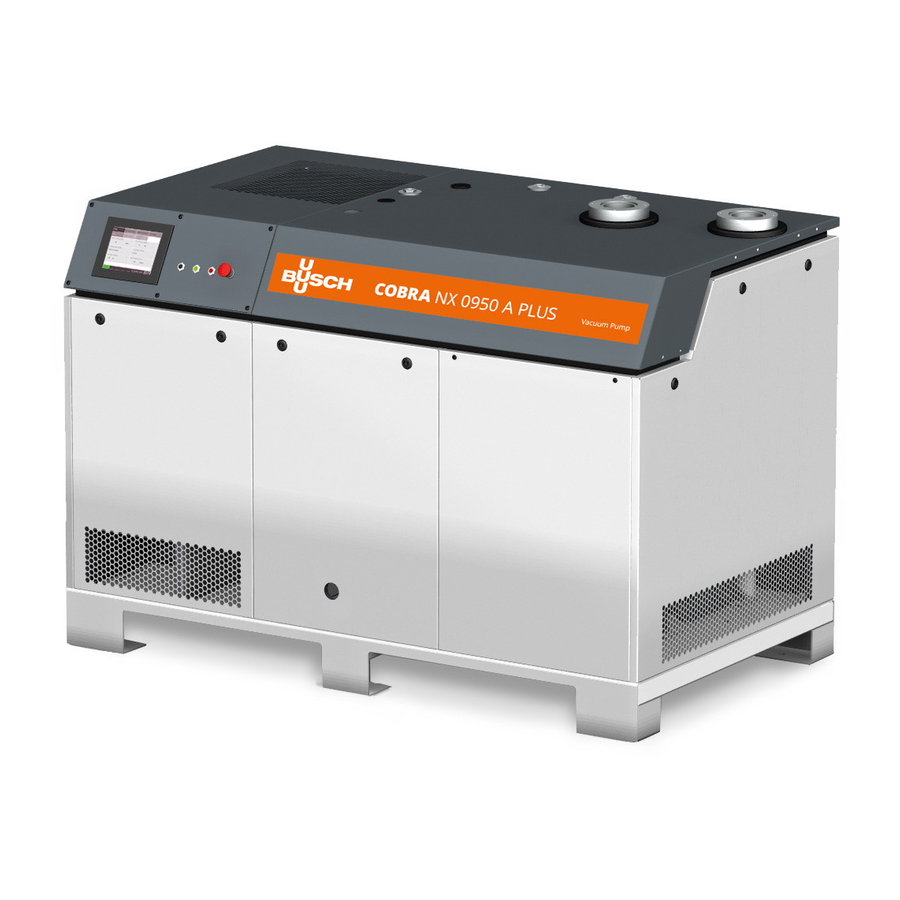
- Page 1 Instruction Manual COBRA PLUS Dry Screw Vacuum Pumps NX 0950 A PLUS Ateliers Busch S.A. Zone industrielle, 2906 Chevenez Switzerland 0870232499/-_en / Original instructions / Modifications reserved 27/01/2021...
-
Page 2: Table Of Contents
Table of Contents Table of Contents 1 Safety ............................4 2 Product Description ........................5 2.1 Operating Principle ......................7 2.2 Application........................7 2.3 Standard Features ......................8 2.3.1 User Interface ......................8 2.3.2 Acoustic Cabinet ....................8 2.3.3 Control Unit ......................8 2.3.4 Monitoring Devices .................... - Page 3 Table of Contents 7.1.2 Local/Auto "Week Planner".................. 34 7.1.3 Remote/Auto ......................35 7.2 Operating Mode ......................36 7.2.1 Speed Control ....................... 36 7.2.2 Pressure Control ....................37 7.3 Ecomode .......................... 37 7.4 Warm-up / Cool-down Modes..................38 7.4.1 Conveying Condensable Vapours ................39 7.5 Inlet Valve Control ......................
-
Page 4: Safety
Safety Prior to handling the machine, this instruction manual should be read and understood. If anything needs to be clarified, please contact your Busch representative. Read this manual carefully before use and keep for future reference. This instruction manual remains valid as long as the customer does not change anything on the product. -
Page 5: Product Description
Product Description | 2 Product Description Acoustic cabinet Alarm indicator light Barrier gas connection Cooling air inlet Cooling air outlet Condensate drain Cooling fan I/O port (D-Sub 9) Control unit Cooling water inlet Cooling water outlet Emergency stop switch User interface (human-machine) Suction connection Communication port (Modbus TCP/IP) Nameplate... - Page 6 2 | Product Description Vacuum pump (VP) PSA1 PSA2 Barrier gas connection Barrier gas flow meter Barrier gas manometer Barrier gas pressure regulator Solenoid valve (barrier gas) Condensate drain Cooling water drain plug Cooling water inlet Cooling water outlet Eye bolt Gas ballast valve Suction connection Inlet screen...
-
Page 7: Operating Principle
Some of the HMI illustrations which are shown in this manual are taken from the HMI display of the "R5 RA 0760 A PLUS" vacuum pump. Although they may differ slightly for the "COBRA NX 0950 A PLUS" vacuum pump, the principles of using of the inter- face however are similar. -
Page 8: Standard Features
- Steel - Stainless Steel - Aluminium - Fluoroelastomer (FKM/FPM) • In doubt, please contact your Busch representative. 2.3 Standard Features 2.3.1 User Interface A user interface, also termed human-machine interface (HMI), allows the control, monit- oring and configuration of the machine via a 7.5” touchscreen. -
Page 9: Gas Ballast Valve
Product Description | 2 2.3.6 Gas Ballast Valve The gas ballast valve mixes the process gas with a limited quantity of ambient air to counteract the condensation of vapour inside the machine. The gas ballast valve has an influence on the ultimate pressure of the machine, see Tech- nical Data [► 69]. -
Page 10: Oil Level Switches
2 | Product Description 2.3.12 Oil Level Switches The machine is equipped with two oil level switches to monitor the oil levels at the motor and suction sides. 2.3.13 Exhaust Pressure Sensor The machine is equipped with an exhaust pressure sensor to monitor the back pressure at the discharge. -
Page 11: Led Indicators
Product Description | 2 2.5 LED Indicators Next to the user interface, there are three LED’s which give a visual indication of the ma- chine state. Start/stop button (SSB) Power indicator light (PIL) Alarm indicator light (AIL) The LED is green when The LED is green when The LED flashes in red the machine is running... -
Page 12: Bottom Bar
2 | Product Description – The tab “MAINTENANCE” displays the history of malfunctions, maintenance inter- vals and operating curves. HOME OPERATIONS MAINTENANCE SYSTEM HISTORY SERVICE TREND – The tab “SYSTEM” allows to set or change settings, provides information about the product and its distributor. -
Page 13: Role And User
– set the remote control and monitoring parameters, refer to the specific document "Pump Control Instructions, art. no.: 0870213261". – Role 3 ► Busch Service Only authorized personnel from Busch Service have this level of access rights. NOTE In case of any questions related to the machine settings: •... -
Page 14: System Settings
Thresholds can only be changed by Busch Service “Role 3”, see the predefined factory settings in the chapter Warnings and Alarms Thresholds [► 50]. NOTE Advanced settings Advanced settings can only be changed by Busch Service “Role 3”, refer to the specific document "Pump Control Instructions, art. no.: 0870213261". 14 / 72 0870232499_NX0950A_PLUS_-_IM_en... -
Page 15: Machine And Software Identification
Product Description | 2 2.6.6 Machine and Software Identification To display the machine and software identification: • Go to “SYSTEM” > “MODEL”. MAINTENANCE SYSTEM HOME OPERATIONS SETTINGS CONTACT MODEL ETHERNET Vacuum pump type Vacuum pump model COBRA PLUS NX 0950 A Software HMI Software PLC Serial number... -
Page 16: Web Visualization
2 | Product Description SYSTEM HOME MAINTENANCE OPERATIONS SETTINGS MODEL ETHERNET CONTACT Ethernet settings Change settings Current IP address New IP address 192 . 168 . Current subnet mask New subnet mask 255 . 255 . 255 . Current gateway New gateway 192 . - Page 17 Product Description | 2 • Open your web browser (full screen window) and type the IP address of the machine to monitor in the address bar, followed by: :8080/smartpump.htm. By default, the whole address to be typed in the web browser is: 192.168.0.22:8080/smartpump.htm •...
- Page 18 2 | Product Description • The second page “Service” shows the service table of the machine and Busch service contact information. • The third page “My vacuum pump” gives general information about the machine. NOTE • Contact Busch: ð If the Ethernet port of the machine (COM) is already used for remote control / monitoring purpose.
-
Page 19: Transport
Transport | 3 Transport WARNING Suspended load. Risk of severe injury! • Do not walk, stand or work under suspended loads. WARNING Transport and lifting. Risk of severe injury! • Lift the machine from underneath with care to prevent the load from tipping over. •... -
Page 20: Storage
4 | Storage ¼ Remove side cover • Replace the side cover. Storage • Seal all apertures with adhesive tape or reuse provided caps. NOTICE Long storage time. Risk of damage to the machine! • Due to a long storage time the capacitors of the variable-frequency drive can lose effi- ciency because of electrochemical processes. -
Page 21: Installation
• Make sure that the cooling water complies with the requirements, see Cooling Water Connection [► 23]. If the machine is installed at an altitude greater than 1000 meters above sea level: • Contact your Busch representative, the ambient temperature should be limited. 0870232499_NX0950A_PLUS_-_IM_en 21 / 72... -
Page 22: Connecting Lines / Pipes
In case of very long connection lines it is advisable to use larger line sizes in order to avoid a loss of efficiency. Seek advice from your Busch representative. • Make sure that the connection flanges are fitted with the appropriate gaskets. -
Page 23: External Inlet Pressure Sensor
Installation | 5 5.2.3 External Inlet Pressure Sensor An external inlet pressure sensor can be connected to the Control Unit. To control the machine with an external sensor: – Mechanically fit the Pressure Sensor at the desired location upstream of the vacuum pump inlet (on a vacuum vessel or in the vacuum chamber for instance). -
Page 24: Barrier Gas System Connection
5 | Installation • To reduce the maintenance effort and ensure a long product lifetime we recommend the following cooling water quality: Hardness mg/l (ppm) < 90 Properties Clean & clear PH value 7 ... 8 Particle size µm < 200 Chloride mg/l <... -
Page 25: Filling Oil
Risk of premature failure! Loss of efficiency! • Only use an oil type which has previously been approved and recommended by Busch. For oil type and oil capacity see Technical Data [► 69] and Oil [► 69]. Oil filling at the motor side ¼... - Page 26 Last oil change __ / __ / ____ Oil type see nameplate Change interval see instruction manual If there is no sticker (part no. 0565 568 959) on the machine: • Order it from your Busch representative. 26 / 72 0870232499_NX0950A_PLUS_-_IM_en...
-
Page 27: Gas Ballast Opening And Closing
Installation | 5 5.4 Gas Ballast Opening and Closing Open position ¼ Remove central back cover Quarter turn key (delivered loose) Closed position 0870232499_NX0950A_PLUS_-_IM_en 27 / 72... -
Page 28: Electrical Connection
• Provide an overload protection according to EN 60204-1 for the machine. • Busch recommends installing a C-curve circuit breaker. • Make sure that the variable-frequency drive, the motor and other electrical devices will not be affected by electric or electromagnetic disturbance from the mains; if ne- cessary seek advice from Busch. -
Page 29: Wiring Diagram Control Unit
Installation | 5 5.5.1 Wiring Diagram Control Unit Internal view of the control unit: PLC1 DO1DI1 AI1 on EMC filter Filter L1 L2 L3 Box fan Power input Customer power supply: Wire gauge according to EN 60204-1 Power supply 3L+PE 380-440V +/-5% 50/60Hz Lockable disconnect switch Overload protection... -
Page 30: Commissioning
6 | Commissioning Air flow (blowing) If the rotation must be changed: • Switch any two of the phase wires. Commissioning 6.1 Prerequisites Before Use NOTICE The machine can be shipped without oil. Operation without oil will ruin the machine in short time! •... -
Page 31: Configuration
– Inlet Valve Control [► 40], – Vacuum Booster Control [► 42]. Do not hesitate to contact Busch to get any further information about the configuration of your machine. • Click on the “Help” icon in the bottom bar to get the contact information of your Busch representative, see Bottom Bar [► 12]. - Page 32 6 | Commissioning NOTICE Lubricating a dry running machine (compression chamber). Risk of damage to the machine! • Do not lubricate the compression chamber of the machine with oil or grease. CAUTION During operation the surface of the suction and exhaust connections may reach temper- atures of more than 70°C.
-
Page 33: In Operation
In Operation | 7 In Operation CAUTION During operation the surface of the suction and exhaust connections may reach temper- atures of more than 70°C. Risk of burns! • Avoid contact with these surfaces during and directly after operation. CAUTION Remove covers during operation. -
Page 34: Local/Manual
7 | In Operation 7.1.1 Local/Manual Configured by default, this mode allows to control manually the machine directly from the user interface (HMI). Control mode Manual Auto Local Start / Stop Digital speed control Remote Analog speed control Modbus control 7.1.2 Local/Auto "Week Planner"... -
Page 35: Remote/Auto
Control mode Manual Auto Local Start / Stop Digital speed control Remote Analog speed control Modbus control • Refer to the specific document “Pump Control Instructions, art. no.: 0870213261” for more details or contact your Busch representative. 0870232499_NX0950A_PLUS_-_IM_en 35 / 72... -
Page 36: Operating Mode
7 | In Operation WARNING The machine may start without notice. Risk of severe injury! As soon as the “Remote” mode is activated: • Make sure the machine is fully operational. 7.2 Operating Mode To access the operating mode menu: •... -
Page 37: Pressure Control
• For smooth process pressure control, it is required to adjust the PID parameters. • Refer to the specific document “Pump Control Instructions, art. no.: 0870213261” for more details or contact your Busch representative. NOTE Display of the ultimate pressure. -
Page 38: Warm-Up / Cool-Down Modes
7 | In Operation SYSTEM HOME MAINTENANCE OPERATIONS PARAMETERS WEEK PLANNER MODE Ecomode Time delay 10 s Ecomode pressure Restart pressure 20 mbar 100 mbar PREVIOUS NEXT • Press a value to change it. Parameter Default value Adjustment range Ecomode pressure 20 mbar 5 …... -
Page 39: Conveying Condensable Vapours
For more effectiveness, make sure that the gas ballast valve is open (see Gas Ballast Opening and Closing [► 27]). Water vapour within the gas flow is tolerated within certain limits. The conveyance of other vapours shall be agreed upon with Busch. If condensable vapours are to be conveyed: • Open the isolation 30 minutes •... -
Page 40: Inlet Valve Control
7 | In Operation 7.5 Inlet Valve Control This menu allows the control and setting of the opening parameters of an isolation valve installed at the suction side of the vacuum pump (not included in the scope of delivery of the vacuum pump). - Page 41 In Operation | 7 PLUS Pump control unit Inlet Valve command line 24VDC from PLUS Pump Max 1A X1 0VDC Customer side Power line from Customer customer with relay appropriate protection Customer Inlet valve Inlet Valve Wiring Diagram NOTE The installation of an isolation valve at the vacuum pump inlet also requires the installa- tion of an external pressure sensor to control the vacuum pump, see External Inlet Pres- sure Sensor [► 23].
-
Page 42: Vacuum Booster Control
7 | In Operation 7.6 Vacuum Booster Control This menu allows the control and setting of the start-up parameters of a vacuum booster installed at the suction side of the vacuum pump (not included in the scope of delivery of the vacuum pump). - Page 43 Vacuum Booster Vacuum Booster Wiring Diagram NOTICE Vacuum booster compatibility. Risk of damage to the machine! • Contact Busch to check the compatibility of the vacuum booster with the vacuum pump and the recommended starting pressure. 0870232499_NX0950A_PLUS_-_IM_en 43 / 72...
-
Page 44: Monitoring
7 | In Operation 7.7 Monitoring 7.7.1 Operating Information This display “HOME” > “MAIN” corresponds to the principal menu and is automatically loaded when the machine is started. It displays the principal operating information. HOME MAINTENANCE SYSTEM OPERATIONS ALARM MAIN MONITORING Inlet pressure Rotation speed... -
Page 45: Operating Data
In Operation | 7 7.7.2 Operating Data This display “HOME” > “MONITORING” displays operating values, it is divided into three different screens. Screen 1 HOME OPERATIONS MAINTENANCE SYSTEM ALARM MAIN MONITORING > Barrier gas solenoid valve Exhaust pressure Open 960 mbar g Instant absorbed power Mean absorbed power 11.5 kW... - Page 46 7 | In Operation Screen 2 HOME OPERATIONS MAINTENANCE SYSTEM ALARM MAIN MONITORING Pump temperature Water flow 40 °C ≤ 2 l/min Oil level Motor frequency 72 Hz PREVIOUS NEXT Pump temperature: Indicates the pump coolant temperature, in case of a too high temperature a warning or an alarm occurs, see Dysfunction [► 50].
- Page 47 In Operation | 7 Screen 3 HOME OPERATIONS MAINTENANCE SYSTEM MAIN MONITORING ALARM Energy consumption since last reset Reset energy consumption (Press button 5s) 921 kWh Energy consumption total Motor start counter 5412 kWh Inlet filter pressure differential Option not selected PREVIOUS NEXT Energy consumption since last reset:...
-
Page 48: History
7 | In Operation 7.7.3 History This display “MAINTENANCE” > “HISTORY” shows the history of: – Events ► Parameter changes, function activation, etc… – Alarms ► Alarm signals from sensors – Warnings ► Warning signals from sensors – Service ► Service tasks completed It is possible to filter the type of message by selecting a specific tab. -
Page 49: Operating Curves
In Operation | 7 7.7.4 Operating Curves This display “MAINTENANCE” > “TREND” shows the trend curve of certain operating values. It offers the possibility to change the time lapse and the curve of six different operating values. MAINTENANCE SYSTEM HOME OPERATIONS HISTORY SERVICE... -
Page 50: Dysfunction
7 | In Operation 7.8 Dysfunction 7.8.1 Warnings and Alarms Thresholds When the machine has reached the limit threshold of an operating value, which is pre- defined in the system, a signal is sent and visible in the bottom bar. There are two signal levels: –... -
Page 51: Warning/Alarm Acknowledgment Procedure
NOTE Threshold values are preset with the factory settings. However, depending on the applic- ation, it is possible to adjust the threshold values only after Busch approval. Threshold changes are only available for "Role 3" users. 7.8.2 Warning/Alarm Acknowledgment Procedure... -
Page 52: Stop The Machine
8 | Maintenance 7.9 Stop the Machine To stop the machine: • Press and hold the start/stop button (SSB) for at least 3 seconds. In case of emergency stop: • Push the emergency stop switch (ESS). As long as the power indicator light (PIL) is green, the machine is still powered. NOTE Control mode “Remote/Auto”. -
Page 53: Maintenance Schedule
Failing to properly maintain the machine. Risk of injuries! Risk of premature failure and loss of efficiency! • Respect the maintenance intervals or ask your Busch representative for service. • Turn off the water supply. If the machine is equipped with a barrier gas system: •... - Page 54 Every 25000 hours, at the • Have a major overhaul on the machine (contact latest after 4 years Busch). To visualise information about remaining hours: • Go to “MAINTENANCE” > “SERVICE”. • Check when the maintenance tasks have to be performed and how long the machine has operated since the first commissioning or last maintenance task.
-
Page 55: Oil Level Inspection
Maintenance | 8 8.2 Oil Level Inspection If the oil level is too low, an alarm signal will be sent by the monitoring system. To check the oil level status: • Go to “HOME” > “MONITORING”. • In the cell “Oil level” it must always be written “OK”. To perform a visual control of the oil level: •... -
Page 56: Cleaning The Inlet Screen
8 | Maintenance 8.3 Cleaning the Inlet Screen Remove side cover ¼ Quarter turn key (delivered loose) Compressed air Pressure sensor Inlet screen • Prior to instruction 5, disconnect the pressure sensor. • Wear protective glasses and a mask to clean with compressed air. •... -
Page 57: Cleaning The Gas Ballast Filter
Maintenance | 8 8.4 Cleaning the Gas Ballast Filter • Close the gas ballast valve. Open position ¼ Remove central back cover Quarter turn key (delivered loose) Closed position • Remove the gas ballast filter with a 36 mm wrench. •... -
Page 58: Cleaning The Silencer
8 | Maintenance 8.5 Cleaning the Silencer Remove side cover ¼ ¼ Quarter turn key (delivered loose) Remove central front cover Remove the exhaust flange of the silencer* through the hole in the cabinet cover Tilt the silencer before removing it through the side of the cabinet. - Page 59 Maintenance | 8 NOTE *Removal of the exhaust flange. When removing the exhaust flange, the Teflon sealing tape will be deteriorated and no longer usable! • Make sure to apply a new Teflon sealing tape before reassembling the flange. Use compressed air and cleaning clothes to clean the inside and outside of the silencer...
-
Page 60: Oil Change
NOTICE Use of an inappropriate oil. Risk of premature failure! Loss of efficiency! • Only use an oil type which has previously been approved and recommended by Busch. At the motor side ¼ At the suction side Remove central back cover ¼... - Page 61 Maintenance | 8 Oil draining at the motor side Cleaning cloth Magnetic plug Drain pan Oil draining at the suction side Cleaning cloth Magnetic plug Drain pan 0870232499_NX0950A_PLUS_-_IM_en 61 / 72...
- Page 62 8 | Maintenance For oil type and oil capacity see Technical Data [► 69] and Oil [► 69]. Oil filling at the motor side ¼ Remove central back cover Quarter turn key (delivered loose) Check oil level Oil filling at the suction side Remove side cover ¼...
-
Page 63: Machine Cleaning
Change interval see instruction manual If there is no sticker (part no. 0565 568 959) on the machine: • Order it from your Busch representative. 8.7 Machine Cleaning • Clean the cooling air inlet and outlet (CAI/CAO) with pressurised air, especially when the machine is in a dusty environment. -
Page 64: Overhaul
• Decontaminate the machine as much as possible and state the contamination status in a ‘Declaration of Contamination’. Busch will only accept machines that come with a completely filled in and legally binding signed ‘Declaration of Contamination’ (form downloadable from www.buschvacuum.com). -
Page 65: Spare Parts
Use of non-Busch genuine spare parts. Risk of premature failure! Loss of efficiency! • The exclusive use of Busch genuine spare parts and consumables is recommended for the correct functioning of the machine and to validate the warranty. Spare parts available: Quantity Description Part no. - Page 66 Busch). Solid foreign matter has • Remove the solid foreign entered the machine. matter or repair the ma- chine (contact Busch). • Check the inlet screen (IS) at the suction connection. The machine does not reach Suction or discharge lines •...
- Page 67 (pressure dersized for the application. work. control mode only). Leaks or pressure drops in • Ask Busch for advice. the pipework upstream the suction connection. Communication problems A wire is broken or not con- • Check the wiring between when the machine is re- nected.
- Page 68 The analog input module is • Refer to schematic and connected not connected or has been reconnect the analog in- disconnected. put module. For the solution of problems not mentioned in the troubleshooting chart contact your Busch representative. 68 / 72 0870232499_NX0950A_PLUS_-_IM_en...
-
Page 69: Technical Data
Technical Data | 13 13 Technical Data NX 0950 A PLUS Pumping speed (72Hz) m³/h Ultimate pressure (without gas ballast) hPa (mbar) abs. ≤0.01 Ultimate pressure (with gas ballast) hPa (mbar) abs. ≤0.05 Nominal motor rating (72Hz) 18.5 Permitted motor speed range 1200 …... -
Page 70: Eu Declaration Of Conformity
This Declaration of Conformity and the CE-mark affixed to the nameplate are valid for the machine within the Busch scope of delivery. This Declaration of Conformity is issued under the sole responsibility of the manufacturer. When this machine is integrated into a superordinate machinery the manufacturer of the superordinate machinery (this can be the operating company, too) must conduct the conformity assessment process for the superordinate machine or plant, issue the Declaration of Conformity for it and affix the CE-mark. - Page 71 Note...
- Page 72 Chile Israel Portugal United Arab Emirates info@busch.cl service_sales@busch.co.il busch@busch.pt sales@busch.ae China Italy Romania United Kingdom info@busch-china.com info@busch.it office@buschromania.ro sales@busch.co.uk Colombia Japan Russia info@buschvacuum.co info@busch.co.jp info@busch.ru info@buschusa.com Czech Republic Korea Singapore info@buschvacuum.cz busch@busch.co.kr sales@busch.com.sg www.buschvacuum.com 0870232499/-_en / © Ateliers Busch S.A.
Need help?
Do you have a question about the COBRA NX 0950 A PLUS and is the answer not in the manual?
Questions and answers