
Related Manuals for BUSCH VACTEST CTR 002


Summary of Contents for BUSCH VACTEST CTR 002
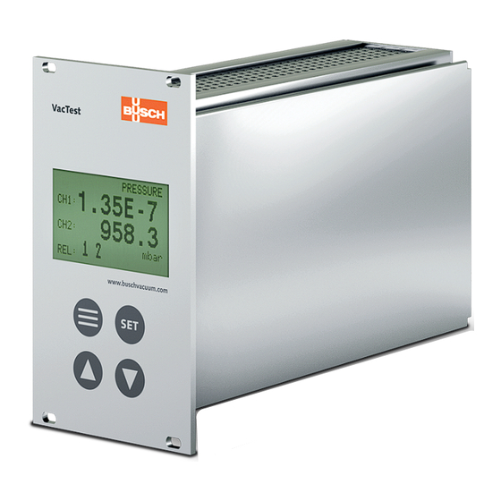
- Page 1 Instruction Manual VACTEST Vacuum Measurement Equipment Active Sensor Controller CTR 002/004 0870206026/-_en / Original instructions / Modifications reserved 16/09/2021...
-
Page 2: Table Of Contents
Table of Contents Table of Contents 1 Safety ............................3 2 Product Description ........................4 2.1 Interface Illustration ......................4 2.2 Product Identification ....................... 5 2.3 Delivery Content ......................5 2.4 Proper Use ........................5 2.5 Improper Use ........................5 3 Transport and Storage.......................5 4 Installation..........................6 4.1 Installation Conditions ...................... -
Page 3: Safety
Safety | 1 Safety • Read and follow the instructions of this manual. • Inform yourself regarding hazards, which can be caused by the product or arise in your system. • Comply with all safety instructions and regulations for accident prevention. •... -
Page 4: Product Description
Product Description The devices are designed to display and control absolute pressure. The Active Sensor Controller CTR 002 is compatible with Busch Digital and 0-10 V Analog Transmitters while the CTR 004 can only be connected to Digital Transmitters. Up to two (CTR 002) or respectively four (CTR 004) measuring channels can be dis- played and controlled simultaneously. -
Page 5: Product Identification
– Instruction manual 2.4 Proper Use The device serves exclusively to display and control absolute pressure in combination with Busch Vacuum Transmitters. It may only be connected to components specifically provided for such purpose. 2.5 Improper Use The use for purposes not mentioned above is regarded as improper, especially: –... -
Page 6: Installation
4 | Installation Installation CAUTION Unauthorized modifications. Risk to injury! • Modifications or conversions of the gauge are not allowed. 4.1 Installation Conditions • Make sure that the environment of the device is not potentially explosive. • Make sure that the ambient conditions comply with the Technical Data [► 22]. 4.2 Electrical Connection NOTICE Connect transmitters when the controller is powered. -
Page 7: Connecting To Digital Transmitters (Rs485)
Installation | 4 4.2.2 Connecting to Digital Transmitters (RS485) For operation of the gauge with a controller, a suitable connecting cable must be used. CTR 004 CTR 002 VacTest www.buschvacuum.com Active sensor controller With the controller CTR 002: up to 2 gauges can be connected. With the controller CTR 004: up to 4 gauges can be connected. -
Page 8: I/O And Communication Port Schematic
4 | Installation 4.2.4 I/O and Communication Port Schematic For digital transmitter: Connector: D-Sub15, 15-pin, female Pin no. Description Pin no. Description Do not connect Voltage Supply 24 VDC Supply GND RS485, D+ RS485, D- Ground NOTE We recommend to have "Ground" (Pin 12) and supply common (Pin 5) grounded. For analog transmitter: Connector: C91E, 6-pin, female, bolted type Pin Nr. -
Page 9: Setpoint Relays
(TIP) By means of the USB or RS232 interface the controller can be connected to a PC, e.g. for recording measurements or to adjust transmitter parameters in combination with Busch VacTest explorer software. Instruction Manual VACTEST Active Sensor Controler CTR 002_004_EN_en... -
Page 10: Operation
5 | Operation Operation 5.1 Startup • Connect the transmitters. • Wire the control lines of the relay outputs. • Connect the mains. • Switched on the controller. NOTE Afterwards the device will perform a selt-test and scan for connected vacuum transmit- ters while the display shows "scan". -
Page 11: Menu "Pressure" - Pressure Reading
Operation | 5 5.2 Menu "Pressure" - Pressure Reading In display mode the controller shows the actual absolute pressure for two or respectively four channels. Reading is numerical above 1 mbar (Torr, …) and exponential below. Further the display indicates the relay control status (active/inactive) and states of each individual relay (on/off). -
Page 12: Menu "Channel" - Parameters And Functions
5 | Operation 5.3 Menu "Channel" - Parameters and Functions The menu “Channel” shows channel number, transmitter type and the associated pa- rameters and functions which directly affects pressure reading. ch: Channel CHANNEL MENU type: Transmitter type (cannot be edited) gas: Gas type type: DPH 400... - Page 13 Operation | 5 Pre-defined gas selection “gas”: • Press the "set" key several times until the cursor is flashing line "gas". • Select the appropriate gas from the list. • Confirm with "set". User-defined correction factor “corr”: • Press the "set" key several times until the cursor is flashing in the line "corr".
-
Page 14: Transmitter Readjustment "Adjust
5 | Operation 5.3.4 Transmitter Readjustment "adjust" NOTE For transmitters DPC and DPH with combination sensors the adjustment does only affect the Pirani sensor. Hot and cold cathode sensors are not readjusted. • Please refer to the corresponding gauge manual for transmitter readjustment specifi- cations. -
Page 15: Enable/Disable Ionization Sensor "Hcsens" Or "Ccsens
Operation | 5 5.4.1 Enable/Disable Ionization Sensor "HCSens" or "CCSens" These functions are applicable for high vacuum transmitters with combination sensors operating an ionization sensor (hot or cold cathode). For certain vacuum processes it may be necessary to disable the ionization sensor, which is automatically controlled by the transmitter electronics. -
Page 16: Menu "Relay" - Switching Outputs
5 | Operation 5.5 Menu "Relay" - Switching Outputs In the menu “Relay” you can assign the switching outputs and set relay parameters. rel: Relay number RELAY MENU rel: ch/mode: Relay assignment / switching mode on/off: Ionization sensor On/Off ch/mode: ch1 press on: 10 mbar... -
Page 17: Menu "Common" - Display Settings
Operation | 5 Switch off Switch on Relay active Relay inactive Time NOTE If both relays are assigned to one measuring channel a three-state-control can be achieved by appropriate adjustment of the setpoints. 5.6 Menu "Common" - Display Settings In the menu “Common” settings for pressure display and the start mode of pressure control are selected. -
Page 18: Set Background Illumination "Backlight
5 | Operation 5.6.2 Set Background Illumination "backlight" – “on” ► backlight is activated. – “off” ► backlight is deactivate. – autoff ► backlight is switched off automatically after 20 seconds when no key is pressed 5.6.3 Start Mode of Relay Control "start active" –... -
Page 19: Communication
Communication | 6 Communication NOTE The Busch communication protocol is available separately on request. Ask your Busch representative to get the document. 6.1 Device Serial Interface The controller is equipped with serial interfaces RS232 and USB. The settings of the CTR 002 / CTR 004 can be changed via the device address 100. De- vice addresses 1 to 4 enable direct access to the connected transmitters and their param- eters. -
Page 20: Setpoints
• A gap between the thresholds being too small will result in flickering of the relay 6.3 VacTest Explorer Software VacTest explorer software has been especially developed for use with Busch vacuum gauges and is available for Windows and Android operating systems. -
Page 21: Maintenance And Service
Maintenance and Service | 7 Maintenance and Service WARNING Units contaminated with hazardous material. Risk of poisoning! Risk of infection! If the unit is contaminated with hazardous material: • Wear appropriate personal protective equipment. The device requires no maintenance. External dirt and soiling can be removed by a damp cloth. -
Page 22: Technical Data
9 | Technical Data Technical Data Controller CTR 002 Controller CTR 004 Materials exposed to vacuum Compatibility All digital transmitters and 0 All digital transmitters … 10 V analog transmitters Display LCD graphic display, background illumination Display refresh rate Measurement unit mbar, bar, mTorr, Torr, Pa, hPa Inputs 0 …... -
Page 23: Eu Declaration Of Conformity
10 EU Declaration of Conformity This Declaration of Conformity and the CE-mark affixed to the nameplate are valid for the gauge within the Busch scope of delivery. This Declaration of Conformity is issued under the sole responsibility of the manufacturer. - Page 24 Busch Vacuum Solutions We shape vacuum for you. Argentina Denmark Malaysia South Africa info@busch.com.ar info@busch.dk busch@busch.com.my info@busch.co.za Australia Finland Mexico Spain sales@busch.com.au info@busch.fi info@busch.com.mx contacto@buschiberica.es Austria France Netherlands Sweden busch@busch.at busch@busch.fr info@busch.nl info@busch.se Bangladesh Germany New Zealand Switzerland sales@busch.com.bd info@busch.de sales@busch.co.nz...
Need help?
Do you have a question about the VACTEST CTR 002 and is the answer not in the manual?
Questions and answers