Table of Contents
Advertisement
Advertisement
Table of Contents

Related Manuals for oventrop OV-DMC 2


Summary of Contents for oventrop OV-DMC 2
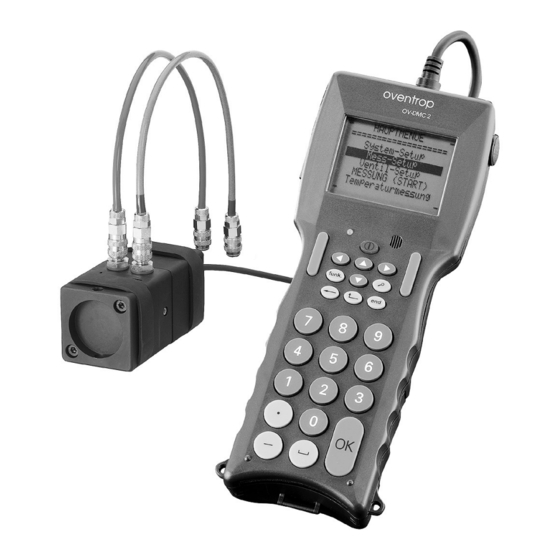
- Page 1 Valves, controls + systems Flow meter “OV-DMC 2” Operating instructions...
- Page 2 Subject to modification without notice. Oventrop does not accept liability for the accuracy of the OV-DMC flow meter readings.
-
Page 3: Table Of Contents
Contents Page Content ................13 General information . -
Page 4: General Information
(see list on next page). When using the “OV-DMC 2” for the regulation of valves which are not produced by Oventrop, the corres - ponding kv-value has to be entered before the first measurement. To do so, the kv-value method is chosen in the menu "Measurement-Setup”. -
Page 5: Characteristic Lines
Characteristic lines Characteristic lines: Characteristic lines of the Oventrop valves: Indicated display Double regulating and commissioning valves “Hycocon V, VTZ, VPZ” DN 15 to DN 40 Hycocon V Regulating valves “Hycocon T, ETZ” DN 15 to DN 25 Hycocon T Regulating valves “Hycocon TM, HTZ”... - Page 6 Characteristic lines Hattersley (stored values taken from the catalogue 2000): Double regulating and commissioning valves: Fig.-No. M737: DN 50 to DN 300 M737 Fig.-No. 1700: DN 15 to DN 50 1700 Fig.-No. 1700L: DN 15 1700L Fig.-No. 1710: DN 15 to DN 50 1710 Metering stations/combinations metering stations/valves: Fig.-No.
-
Page 7: Content Of Measuring Case
19. Allen key 4 mm with black handle 10. Allen key 8 mm with black handle 11. PC connection cable to transmit stored data of the “OV-DMC 2” to the USB interface 12. USB-Stick for data transmission 13. 2 measuring adapters with connection thread R ⁄... - Page 8 13. Measuring head with connection cable, connection nipples for measuring hoses and two rubber rings protecting the measuring head against impact 14. Power pack with connecting cable 15. Temperature sensor with connecting cable 1.0 m long 11. PC connecting cable to transmit stored data of the “OV-DMC 2” to the USB interface...
-
Page 9: Component Connection Diagram/Battery Case
Component connection diagram/Battery case Lockable plug-in connection between flow meter and measuring head: Lockable plug The plug is released by pushing back the sliding sleeve positioning The red positioning point indicates the point position of the guide when introducing Guide the plug into the guiding groove of the Sliding sleeve jack bush on the lower side of the flow... -
Page 10: Technical Data
Technical data Measuring range: Measuring range - differential pressure: -0.05 kPa to 200 kPa Max. static excess pressure: 2000 kPa Measuring range – temperature: -20°C to +120°C Resolution: Differential pressure: 0.01 kPa Flow: 0.0001 l/s Temperature: 0.1°C Accuracy: Differential pressure: up to 10 kPa ±... -
Page 11: Keyboard
Keyboard oventrop OV-DMC 2 The flow meter is activated by using the key . The flow meter is switched on by pressing the key for about 1 second and is switched off by pressing it for about 3 seconds (only possible in the main menu). Before the flow meter switches off completely, some data is saved and it is checked (with the measuring head being connected) whether the bypass inside the measuring head is opened. -
Page 12: Main Menu
If the flow meter is switched on with the measuring head being connected (keep key pressed for about 1 sec.), not only “oventrop” but also the 4- digit number of the flow meter appears in the lower left edge and the 2-digit software version in the lower right edge. -
Page 13: Measurement-Setup
METHOD pressure: mbar flow: l/h Ethylen glycol 35% Valve-Setup VALVE-SETUP Oventrop ---------- Choice of the valve manufacturer by using the keys --------------------- --------------------- OVENTROP Type----------------- Change to valve type by using the key type: Hydrocon Choice of the valve type by using the keys... -
Page 14: Temperature Measurement
Temperature measurement Temperature measurement TEMP.MEASUREMENT Connect the temperature sensor to the flow meter. --------------------- --------------------- Change to temperature measurement by using the key “OK”. Go to main menu by pressing the keys “OK”, after having Temp.: 022.2 °C measured the temperature. Temp.: 072.0 °F An error message will appear on the display if there is no sensor connected. -
Page 15: Temperature Input
Temperature input Temperature input MEASUREMENT-SETUP As for the measuring methods (balanced pressure, computer, kv value and --------------------- --------------------- balance method), the fluid temperature is not only measured but it can also be BALANCED PRESSURE entered directly during glycol measurement in the menu “Measurement Setup”. pressure: mbar flow: l/h To enable a new temperature data entry, the previously displayed temperature... -
Page 16: Measurement
Measurement Balanced pressure method Measurement Some measurements are started directly from the menu “Valve-Setup” (“Cocon” valves and metering stations). The sequence of measurement is simi- lar to the kv-value method and is also described under that point. For all other regulating valves, the menu “Measurement-Setup”, offers different measuring methods: Balanced pressure method/Data logging Differential pressure measurement... -
Page 17: Data Logging
Data Logging Data Logging: Here, several measurements are carried out at different BALANCED PRESSURE intervals and are stored in the memory of the flow meter as consecutive valve --------------------- --------------------- numbers. Hydrocon R DN 020 The data logging function is possible in the balanced pressure method and presetting: when measuring differential pressure. -
Page 18: Kv-Value-Method
Kv-value method Computer-method Kv-value method: The kv-value of the valve to be measured is entered. Input KV-VALUE METHOD is completed by pressing the key “OK”. Now the measuring head is activated --------------------- --------------------- by the flow meter and the bypass is closed automatically. The closing proce- dure is indicated by the rotating symbols in the left and right display corners. -
Page 19: Permanent Measurement Of "Cocon"/"Cocon 4" Valves And Metering Stations
“Cocon”/“Cocon 4” valves/Metering stations Permanent measurement Permanent measurement of “Cocon”/“Cocon 4” valves and metering sta- AKTIV tions: Here, the “Cocon” valve or the metering station are chosen in the menu --------------------- --------------------- “Valve-Setup”. Choice is confirmed by pressing the key “OK” and measurement is started automatically. -
Page 20: Ov-Balance
OV-Balance OV-Balance: This regulation method is an advancement of the compensation method. The advantage of the OV-Balance is that the complete supply system may be balanced by only one person. The time required for the hydronic balance is reduced considerably provided that the installation is structured clearly and a consecutive numbering of all regulating valves is summarised in regulating groups. - Page 21 OV-Balance Before carrying out the on site regulation, it has to be verified whether all isolating valves within the circuit are opened. Moreover it must be ensured that the installation corresponds to the design condition, e.g. ther- mostatic radiator valves preset, thermostatic head removed. Sequence of regulation: 1.
- Page 22 OV-BALANCE VALVE-SETUP manufacturer by using regulating group (e.g. --------------------- --------------------- --------------------- --------------------- the keys cellar) OVENTROP NAME/GROUP NEW Change to valve type Choose first letter by typ e: Hydrocon name: cellar using the key Choice of valve type via group:...
- Page 23 OV-Balance Measurement Enter nominal flow rate OV-BALANCE for valve no. 1 (e.g. 500 --------------------- --------------------- in object l/h). Cellar G.: 1 / 1 Go to next menu win- Hydrocon R DN 20 dow by using the key 3.0 preset’g 0.0 “OK”.
- Page 24 OV-BALANCE manufacturer by using following calculation of --------------------- --------------------- --------------------- --------------------- the keys the presetting values. OVENTROP Change to valve type Go to next menu win- OV-BALANCE type: Hydrocon R dow by using the key size: DN 25 Choice of valve type via CALCULATE ? “OK”.
- Page 25 --------------------- --------------------- --------------------- --------------------- the keys (e.g. 1) CHOOSE GROUP OVENTROP Change to valve type Go to next menu win- name: Cellar type: Hydrocon dow by using the key group: Choice of valve type via “OK”.
- Page 26 OV-Balance New valve User information. Choose calculation OV-BALANCE OV-BALANCE “Yes” by using the --------------------- Go to next menu win- --------------------- in object --------------------- --------------------- keys dow by using the key Go to next menu win- “OK”. Attention OV-BALANCE dow by using the key ? CALCULATE ? enter flow “OK”.
- Page 27 OV-Balance Delete valve Choose name of the Delete valve by pressing OV-BALANCE SETTINGS regulating group (e.g. the keys --------------------- --------------------- --------------------- --------------------- Go to next menu win- cellar). CHOOSE GROUP name: Cellar dow by using the key Go to next menu win- name: Cellar “OK”.
- Page 28 OV-Balance Move valve Choose name of the After successful calcula- OV-BALANCE SETTINGS tion, the presetting regulating group (e.g. --------------------- --------------------- --------------------- --------------------- values can be queried cellar). name: Cellar CHOOSE GROUP according to the valve Go to next menu win- 1 Nr.: 1 name: Cellar numbers (e.g.
-
Page 29: Storage And Printing Of Valve Data
In order to do this, the transmission cable has to be connected to the flow meter and the USB interface. After having selected “Receiving data” on the PC, the programme is waiting for the data of the “OV-DMC 2”. To do this, choose MEMORY the submenu “Print content”... -
Page 30: Example
Example Example of the listing of all stored measured values MAIN MENU Printing the memory content shows the sequence of measurement --------------------- --------------------- SYSTEM-SETUP MEASUREMENT-SETUP Print-out of measured data (example) VALVE-SETUP MEASURE (START) Date: 30.03.00 TEMP. MEASUREMENT Project number: 47/2000 Project: Multiple dwelling unit Address of project:... -
Page 31: Batteries
Adjustment of the contrast of the LCD display. Switch on flow meter by pressing the key Enter access code When the name “Oventrop” appears on the display, keep the key pressed until “please wait” appears. Then ”enter access code” appears. -
Page 32: Functional Messages
Functional messages In the main menu “Measure (start)”, the functional sequence of the measuring head is shown on the display. This message only appears on the screen for a few seconds. The sequence is continued automatically. Attention Close bypass > Yes < Attention Open bypass >... -
Page 33: Error Messages
Solution: Plug in power pack and press key “OK”. The red control lamp on the No power pack flow meter will light up. > Yes < Please contact the company F.W. Oventrop GmbH & Co. KG in case of malfunction and for any further questions. - Page 34 “OV-DMC 2” item no. 106 91 77 with double regulating and commissioning valve “Hydrocontrol VTR”...
- Page 36 OVENTROP GmbH & Co. KG Paul-Oventrop-Straße 1 D-59939 Olsberg Telefon +49 (0)29 62 82-0 Telefax +49 (0)29 62 82-400 E-Mail mail@oventrop.de Internet www.oventrop.com For an overview of our global presence visit www.oventrop.com. 106917791 09/2010...
Need help?
Do you have a question about the OV-DMC 2 and is the answer not in the manual?
Questions and answers