Table of Contents
Advertisement
Quick Links
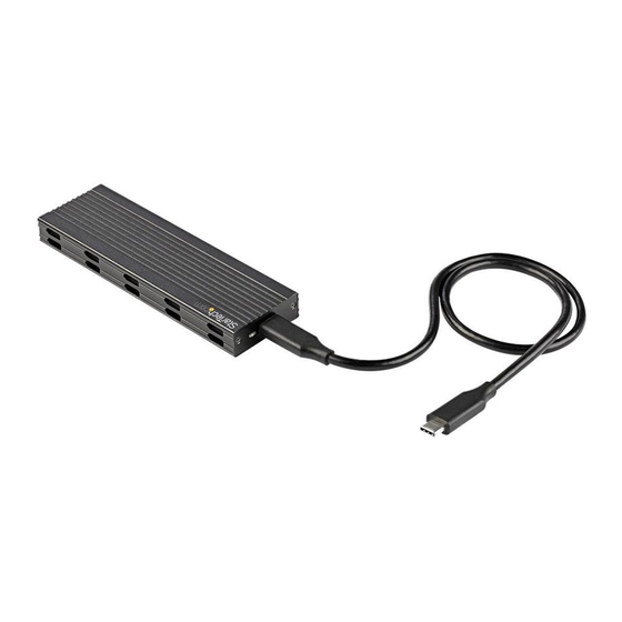
M.2 SATA/NVMe SSD Enclosure - USB 3.2 (10Gbps) w/ USB-C and USB-A Cables
Product Diagram (SM2E1BMU31C)
Exterior - Enclosure
1
Component
• Used to secure the Drive Tray in the
1
Drive-Tray Screws x 2
Enclosure.
• Indicates that the Enclosure is receiving
2
power.
Power & Activity LED
• Blinks during read/write activity.
• Used to connect the Enclosure to the Host
3
USB-C Port
Computer.
Interior - Drive Tray
4
Component
4
Drive Connector
• Used to connect the Drive to the Enclosure.
Adjustable Drive
5
• Used to accommodate different drive lengths.
Length Holes
Drive-Mount Screw/
6
• Used to secure the Drive to the Enclosure.
Standoff/Nut
To view manuals, FAQs, videos, drivers, downloads, technical drawings, and more, visit www.startech.com/support.
To view manuals, FAQs, videos, drivers, downloads, technical drawings, and more, visit www.startech.com/support.
2
3
Function
5
6
Function
Package Contents
• M.2 SSD Enclosure x 1
• USB-C to USB-C Cable x 1
• USB-A to USB-C Cable x 1
• Drive Installation Screw Kit x 1
• Micro Screwdriver x 1
• Quick-Start Guide
Product Information
For the latest requirements, please visit
www.startech.com/SM2E1BMU31C
Product Requirements
• M2 SATA/NVMe SSD x 1
• 30 mm, 42 mm, or 60 mm Drive Length
• Needle-nose Pliers x 2
Installation
Installing a Drive
Warning! Handle drives with care.
1. Remove the Drive Tray Screws (x 2) from the Enclosure, using a Phillips Head
Screwdriver, and remove the Cover Plate.
2. Carefully pull the Drive Tray out of the Enclosure.
3. Remove the Drive-Mount Screw, using a Phillips Head Screwdriver.
4. Place the Drive next to the Drive Tray and align the screw holes in the Drive with
the Adjustable Drive Length Holes on the Drive Tray to determine the desired
Adjustable Drive Length Hole setting.
Note: If the drive mounting hardware is already installed in the correct position,
proceed to step 8.
5. Remove the Drive Standoff and Nut, using two sets of Needle-nose Pliers.
6. Insert the Drive Standoff and Nut into the Adjustable Drive Length Hole (60, 42,
or 30) according to the length of the Drive.
7. Tighten the Standoff and Nut, using two sets of Needle-nose Pliers.
Quick-Start Guide
Manual Revision: April 20, 2021 3:03 PM
Advertisement
Table of Contents

Related Manuals for StarTech.com SM2E1BMU31C


Summary of Contents for StarTech.com SM2E1BMU31C
- Page 1 Standoff/Nut 7. Tighten the Standoff and Nut, using two sets of Needle-nose Pliers. To view manuals, FAQs, videos, drivers, downloads, technical drawings, and more, visit www.startech.com/support. To view manuals, FAQs, videos, drivers, downloads, technical drawings, and more, visit www.startech.com/support. Manual Revision: April 20, 2021 3:03 PM...
- Page 2 StarTech.com. Where they occur these references are for illustrative purposes only and do not represent an endorsement of a product or service by StarTech.com, or an endorsement of the product(s) to which this manual applies by the third-party company in question.
Need help?
Do you have a question about the SM2E1BMU31C and is the answer not in the manual?
Questions and answers