Table of Contents
Advertisement
Available languages
Available languages
WARNING
This appliance is equipped
for (Natural or Propane)
gas. Field conversion is
not permitted other than
between natural or
propane gases.
WARNING: If the information in this manual is not followed exactly, a fire or
explosion may result causing property damage, personal injury, or loss of life.
•
Do not store or use gasoline or other flammable vapors and liquids in the vicinity of this or any
other appliance.
•
WHAT TO DO IF YOU SMELL GAS:
•
Do not try to light any appliance.
•
Do not touch any electrical switch; do not use any phone in your building.
•
Immediately call your gas supplier from a neighbor's phone. Follow the gas supplier's instructions.
•
If you cannot reach your gas supplier, call the fire department.
•
Installation and service must be performed by a qualified installer, service agency, or the gas supplier.
This is an unvented gas-fired heater. It uses air (oxygen) from the room in which it is installed. Provisions
for adequate combustion and ventilation air must be provided. Refer to the AIR FOR COMBUSTION
AND VENTILATION section on page 10 of this manual.
This appliance may be installed in an aftermarket, permanently located, manufactured (mobile)
home, where not prohibited by local codes. This appliance is only for use with propane or natural
gas. This appliance is equipped with a simple means to switch between propane and natural gas.
Field conversion by any other means including the use of a kit is not permitted.
!
CAUTION —FOR YOUR SAFETY
INSTALLER: Leave this manual with the appliance.
CONSUMER: Retain this manual for future reference.
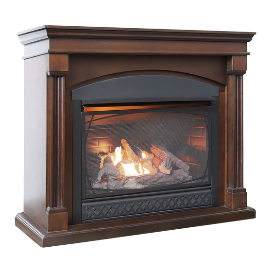
VENT-FREE DUAL FUEL
GAS FIREPLACE HEATER
User's Manual and Operating Instructions
Model:
HHFPDF32F1
Patent
Dual Fuel Technology
ANS Z21.11.2-2019
MC No. 274387
HH2102DFF, 210423
Advertisement
Chapters
Table of Contents

Related Manuals for Hearth & Home HHFPDF32F1


Summary of Contents for Hearth & Home HHFPDF32F1
- Page 1 VENT-FREE DUAL FUEL GAS FIREPLACE HEATER User’s Manual and Operating Instructions Model: HHFPDF32F1 Patent Dual Fuel Technology WARNING This appliance is equipped for (Natural or Propane) gas. Field conversion is not permitted other than between natural or ANS Z21.11.2-2019 propane gases.
-
Page 2: Table Of Contents
Table of Contents Specifications ......................................2 Safety Information ....................................3 Product Identification ..................................6 Hood Assembly to Fireplace ................................7 Mantel Assembly ....................................7 General Preparation ................................... 9 Preparing for Installation .................................10 Installation ......................................13 Log Placement .....................................22 Operation ......................................23 Remote Operation .....................................26 Care and Maintenance ..................................32 Troubleshooting Guide ..................................34 Parts List .........................................37... -
Page 3: Safety Information
Safety Information WARNING WARNING FIRE, EXPOLSION, AND ASPHYXIATION HAZARD Improper adjustment, alteration, service, maintenance, or installation of this heater or its controls can cause death or serious injury. Read the following instructions and precautions in User's Information Manual provided with this heater. - Page 4 Safety Information (cont.) WARNING: • Any safety screen or guard removed for servicing an appliance must be replaced prior to operating the heater. • Any change to this heater or its controls can be dangerous. • Do not use any accessories not approved for use with this heater. •...
- Page 5 Safety Information (cont.) QUALIFIED INSTALLING AGENCY: Only a qualified agency should install and replace gas piping, gas utilization equipment, or accessories, and/or repair and service such equipment. “Qualified agency” means any entity that either in person or through a representative is engaged in and is responsible for: •...
-
Page 6: Product Identification
Product Identification Model: HHFPDF32F1 DUAL FUEL CAPABILITY The heater is equipped to operate on either propane or natural gas. The heater is shipped from the factory ready for connecting to propane. The heater can easily be changed to natural gas by having your qualified installer follow the instructions on page 18 and the markings on the heater. -
Page 7: Hood Assembly To Fireplace
Hood Assembly to Fireplace Secure hood to fireplace with four screws provided as shown. Mantel Assembly 1. Carefully align mounting holes in mantel sides over threaded inserts in mantel base. Secure mantel sides to mantel base with the four screws (two per side) as shown. - Page 8 Mantel Assembly (cont.) 2. Carefully align mounting holes in mantel front over threaded inserts in mantel sides. Secure mantel front to mantel sides with the four screws (two per side) as shown. Do not fully tighten until after final assembly. 3.
-
Page 9: General Preparation
Fireplace to Mantel Assembly Carefully lift the fireplace through the center opening in the front of the fireplace mantel. Slide the fireplace through the opening until the metal trim contacts the front of fireplace mantel. General Preparation LOCAL CODES Install and use the heater with care. Follow all local codes. The installation must conform with local codes or, In the absence of local codes, with the latest edition of The National Fuel Gas Code, ANS Z223.1/NFPA 54*. -
Page 10: Preparing For Installation
Preparing for Installation WATER VAPOR IS A BY-PRODUCT OF UNVENTED ROOM HEATERS Gas combustion creates water vapor as a by-product. Unvented room heaters create about one (1) ounce (30 ml) of water for every 1,000 BTUs (0.3 kW) of gas input per hour. An unvented room heater is recommended as a supplemental heat source for a single room rather than as a primary heat source for an entire house. - Page 11 Preparing for Installation (cont.) DETERMINING FRESH-AIR FLOW FOR THE HEATER LOCATION Determining if You Have a Confined or Unconfined Space: Use the below information to determine if you have a confined or unconfined space. Your space includes the room in which you will install the heater plus any other rooms that are directly connected and have doorless passageways or ventilation grills between the rooms.
- Page 12 Preparing for Installation (cont.) If the area in where the heater operates does not meet the required volume for WARNING indoor combustion air, you must provide combustion and ventilation air by one of the methods described in the NATIONAL FUEL GAS CODE, ANS Z223.1/NFPA 54, the INTERNATIONAL FUEL GAS CODE, or applicable local codes.
-
Page 13: Installation
Installation NOTICE: This heater is intended to be used as a supplemental heating source. Use this heater along with your primary heating system. This heater must not be used as a primary heat source. If you have a central heating system, you may run that system’s circulating blower while using this heater. This helps to circulate the heat around your house. - Page 14 Installation (cont.) HEATER CLEARANCES For convenience and efficiency, install the heater with these points in mind: • Provide easy access for operation, inspection and service. • Install the heater in the coldest part of the room. If this heater is installed directly on carpeting, tile, or other combustible material, other than wood flooring, the heater must be installed on a metal or wood panel that extends the heater’s full width and depth.
- Page 15 Installation (cont.) INSTALLING THE HHFAN100 BLOWER (OPTIONAL) Fig. 4—Grounded Three-Prong Receptacle Electrical grounding instructions: This appliance is WARNING equipped with a three-prong (grounding) plug for your protection against shock hazard and should be plugged directly into a properly grounded three-prong receptacle (See Fig. 4). Disconnect heater from the gas supply before installing the fan Fig.
- Page 16 Installation (cont.) INSTALLING THE BLOWER (OPTIONAL) - continued 4. Route wire harness through channel in the back corner of the fireplace. There are two observation ports on the back of the fireplace to assist in routing the wire harness. Before securing blower assembly to the fireplace, put a wire clip on wire harness and snap into the inside of the fireplace back panel.
- Page 17 Installation (cont.) INSTALLING THE BLOWER (OPTIONAL) - continued Fig. 10—Installing Switch and securing wires 6. Snap Switch into opening in control panel, making sure to position the Auto function on top. Wire clips and a cable tie are provided to help keep the wire harness away from the hot firebox and burner (see Fig.
- Page 18 Installation (cont.) GAS SELECTION INSTRUCTIONS WARNING: This appliance can be used with propane or natural gas. It is shipped from the factory adjusted for use with propane. CAUTION: The knob to the gas selection means shall not be accessed or adjusted while the appliance is in operation.
- Page 19 Installation (cont.) CONNECTING TO A GAS SUPPLY WARNING A qualified service technician must connect heater to gas supply. Follow all local codes. Never connect the heater to private/non-utility gas wells (commonly known as WARNING wellhead gas). CAUTION Never connect the heater directly to the gas supply. This heater requires an external regulator (not supplied).
- Page 20 Installation (cont.) CAUTION Use pipe joint sealant that is resistant to gas (propane or NG). We recommend that you install a sediment trap in a supply line, which traps moisture and contaminants. The sediment trap should be located within reach for cleaning and where it is not likely to freeze. Install it in the piping system between the fuel supply and heater.
- Page 21 Installation (cont.) CHECKING GAS CONNECTIONS After installing or servicing the heater, test all gas piping and connections for leaks. WARNING Immediately correct all leaks. Never use an open flame to check for a leak. Apply a mixture of liquid soap and water WARNING to all joints—bubbles may indicate a leak.
-
Page 22: Log Placement
Log Placement Failure to position the parts in accordance with these diagrams or failure to use only parts WARNING specifically approved with this heater may result in property damage or personal injury. Number of Logs: 7 Check to ensure that no yellow flame comes in CAUTION contact with any log, both after installation and periodically afterwards. -
Page 23: Operation
Operation FOR YOUR SAFETY READ BEFORE LIGHTING If you do not follow these instructions exactly, a fire or explosion may result WARNING causing property damage, personal injury or loss of life. A. This appliance has a pilot that must be lighted by the piezo ignitor. When lighting the pilot, follow these instructions exactly. - Page 24 LIGHTING INSTRUCTIONS 1. STOP! Read all the above safety information before proceeding. Fig. 20—Receiver and Control Knob 2. Open the Lower Access Panel located below the heater screen. 3. Set the receiver switch to the “ON” position (see Fig. 20). Turn the control knob clockwise to the “OFF”...
- Page 25 Operation (cont.) INSPECTING BURNERS Check the pilot flame pattern and burner flame patterns often. PILOT FLAME PATTERN Figure 23 shows a correct pilot flame pattern. Figure 24 shows an incorrect pilot flame pattern. The incorrect pilot flame is not touching the thermocouple. This will cause the thermocouple to cool. When the thermocouple cools, the heater will shut down.
-
Page 26: Remote Operation
Remote Control Operation IF YOU CANNOT READ OR UNDERSTAND THESE INSTALLATION INSTRUCTIONS, WARNING DO NOT ATTEMPT TO INSTALL OR OPERATE THIS DEVICE. This remote control system was developed to provide a convenient, user-friendly, and safe remote control system for gas heating appliances. The system is operated manually from the remote/transmitter and operates on radio frequencies (RF) within a 20-foot range using non-directional signals. - Page 27 Remote Control Operation (cont.) Fig. 26—LCD Screen 1. TEMP Temperature indication. 2. DISPLAY Indicates CURRENT room temperature. 3. FLAME Indicates burner/valve in operation. 4. A: Thermostat function. 5. M: Manual function. 6. SET Remote control battery display 7. °C to °F Temperature in degrees F or C.
- Page 28 Remote Control Operation (cont.) Fig. 29—Thermostat Function Thermostat Function (see Fig. 29): When used as a vented decorative appliance, use of the thermostat function is prohibited—operate manually only. This remote control system can be thermostatically controlled when the control is in the A mode.
- Page 29 Remote Control Operation (cont.) Functions: • When the slide switch is in the REMOTE position, the system only operates if the receiver can receive commands from the remote/transmitter. • When first used or after extended disuse, the “ON” button may have to be pressed for up to three (3) seconds before the valve is activated.
- Page 30 Remote Control Operation (cont.) GENERAL INFORMATION Communication/Safety/Remote-Transmitter Built into the remote control’s software is a COMMUNICATION/SAFETY function. It provides an extra margin of safety when the remote/transmitter is out of the normal 20-foot operating range of the receiver. The COMMUNICATION/SAFETY feature operates the same in all operating modes. In all operating modes and at all times, the remote/transmitter sends an RF signal every 15 minutes to the receiver.
- Page 31 Remote Control Operation (cont.) Remote/Transmitter Wall Clip (see Fig. 33): Fig. 33— Remote/Transmitter Wall Clip You can hang the remote/transmitter on a wall using the provided clip. If installing on a solid wood wall, drill 1/8" pilot holes and use the provided screws. If installing on a plaster/ wallboard wall, first drill two 1/4"...
-
Page 32: Care And Maintenance
Care and Maintenance BURNER FLAME PATTERN Figure 34 shows a correct burner flame pattern. Figure 35 shows an incorrect burner flame pattern. The incorrect burner flame pattern shows sporadic, irregular flame tipping. The flame should not be dark or have an orange/reddish tinge. NOTE: When using the heater the first time, the flame will be orange for approximately one hour. - Page 33 Care and Maintenance (cont.) 1. Shut off the heater, including the pilot. Allow the heater to cool for at least 30 minutes. 2. Inspect the burner, pilot, and primary air inlet holes on the orifice holder for dirt and debris (see Fig. 36). 3.
-
Page 34: Troubleshooting Guide
Troubleshooting Guide WARNING If you smell gas, do the following: • Shut off gas supply. • Do not try to light any appliance. • Do not touch any electrical switch; do not use any phone in your building. • Immediately call your gas supplier from a neighbor’s phone . Follow the gas supplier’s instructions. •... - Page 35 Troubleshooting Guide (cont.) Problem Possible Cause Solution 1. Control knob is not fully pressed in. 1. Press in control knob fully. 2. Control knob is not pressed in 2. After ODS/pilot lights, keep control knob pressed long enough. in 30 seconds. ODS/pilot lights but 3.
- Page 36 Troubleshooting Guide (cont.) Problem Possible Cause Solution White powder 1. When heated, the vapors from 1. Turn heater off when using furniture polish, wax, carpet cleaner or similar products. residue is forming furniture polish, wax, carpet within burner box or cleaners, etc.
-
Page 37: Parts List
Parts List For replacement parts, contact Hearth & Home Dynamics at 1-888-534-1578. Vent-Free Gas Fireplace User’s Manual... -
Page 38: Limited Warranty
WARRANTY KEEP THIS WARRANTY Always specify model and serial numbers when communicating with customer service. We reserve the right to amend these specifications at any time without notice. The only warranty applicable is our standard written warranty. We make no other warranty, expressed or implied. LIMITED WARRANTY HEARTH &... - Page 39 NOTES Vent-Free Gas Fireplace User’s Manual...
- Page 41 CALENTADOR A GAS DE DOS COMBUSTIBLES TIPO CHIMENEA SIN VENTILACIÓN Manual del usuario e instrucciones de funcionamiento Modelo: HHFPDF32F1 Patente Tecnología de dos combustibles ADVERTENCIA: Este aparato está equipado para gas (natural o propano). No se permite la conversión en el campo, ANS Z21.11.2-2019...
-
Page 42: Especificaciones
El incumplimiento de estas instrucciones puede provocar lesiones personales u ocasionar un peligro de incendio y anulará la garantía. Solo un instalador calificado, agente de servicio o proveedor de gas local puede instalar y dar servicio a este producto. N.º de modelo: HHFPDF32F1 Máx. Clasificación de entrada 32,000 32,000 (BTU/h) Mín. -
Page 43: Información De Seguridad
Información de seguridad ADVERTENCIA: PELIGRO DE INCENDIO, EXPLOSIÓN Y ASFIXIA El ajuste, la alteración, el servicio, el mantenimiento o la instalación inadecuados de este calentador o sus controles puede causar lesiones graves o la muerte. Lea las siguientes instrucciones y precauciones en el Manual del usuario que se proporciona con este calentador. - Page 44 Información de seguridad (cont.) ADVERTENCIA: • Antes de hacer funcionar el calentador, se debe reemplazar cualquier pantalla o protector de seguridad que se haya quitado para el mantenimiento del aparato. • Cualquier cambio en este calentador o sus controles puede ser peligroso. •...
- Page 45 Información de seguridad (cont.) AGENCIA DE INSTALACIÓN CALIFICADA: Solo una agencia calificada debe instalar y reemplazar tuberías de gas, equipos de utilización de gas o accesorios, y/o reparar y dar mantenimiento a dichos equipos. “Agencia calificada” significa cualquier entidad que, ya sea en persona o a través de un representante, participa y es responsable de: •...
-
Page 46: Identificación De Producto
Identificación de producto Modelo: HHFPDF32F1 Repisa de la chimenea Campana Pantalla Rejilla Botón de Perilla de encendido Compartimiento control Receptor de la batería Quemador CAPACIDAD PARA DOS COMBUSTIBLES El calentador está equipado para funcionar con propano o gas natural. El calentador se envía desde la fábrica listo para conectarlo a propano. -
Page 47: Ensamble De La Campana A La Chimenea
Ensamble de la campana a la chimenea Asegure la campana a la chimenea con los cuatro tornillos provistos como se muestra. Conjunto de repisa para chimenea 1. Alinee cuidadosamente los orificios de montaje en los lados de la repisa sobre los insertos roscados en la base de la repisa. - Page 48 Montaje de la repisa (cont.) 2. Alinee cuidadosamente los orificios de montaje del frente de la repisa sobre los insertos roscados en los lados de la repisa. Asegure el frente de la repisa a los lados de la repisa con los cuatro tornillos (dos por lado) como se muestra.
-
Page 49: Preparación General
Montaje de la chimenea en la repisa Levante con cuidado la chimenea a través de la abertura central en la parte delantera de la repisa de la chimenea. Deslice la chimenea a través de la abertura hasta que la moldura metálica haga contacto con el frente de la repisa de la chimenea. -
Page 50: Preparación Para La Instalación
Preparación para la instalación EL VAPOR DE AGUA ES UN SUBPRODUCTO DE LOS CALENTADORES DE HABITACIÓN SIN VENTILACIÓN La combustión de gas crea vapor de agua como un subproducto. Los calentadores de habitación sin ventilación crean aproximadamente una (1) onza (30 ml) de agua por cada 1,000 BTU (0.3 kW) de entrada de gas por hora. Se recomienda un calentador de habitación sin ventilación como fuente de calor suplementaria para una habitación individual, en lugar de como fuente de calor principal para toda una casa. - Page 51 Preparación para la instalación (cont.) DETERMINACIÓN DEL FLUJO DE AIRE FRESCO PARA LA UBICACIÓN DEL CALENTADOR Cómo determinar si tiene un espacio confinado o no confinado: Utilice la siguiente información para determinar si tiene un espacio confinado o no confinado. Su espacio incluye la habitación en la que instalará...
- Page 52 Preparación para la instalación (cont.) ADVERTENCIA: Si el área en la que funciona el calentador no cumple con el volumen requerido para el aire de combustión interior, debe proporcionar aire de combustión y ventilación a través de uno de los métodos descritos en el código NATIONAL FUEL GAS CODE, ANS Z223.1/NFPA 54, el código INTERNATIONAL FUEL GASCODE, o los códigos locales correspondientes.
-
Page 53: Instalación
Instalación AVISO: Este calentador está diseñado para usarse como fuente de calor suplementaria. Use este calentador junto con su sistema de calefacción principal. Este calentador no debe utilizarse como fuente de calor principal. Si tiene un sistema de calefacción central, puede hacer funcionar el soplador de circulación de ese sistema mientras usa este calentador. - Page 54 Instalación (cont.) ESPACIOS LIBRES PARA EL CALENTADOR Para mayor comodidad y eficiencia, instale el calentador teniendo en cuenta estos puntos: • Proporcione fácil acceso para el funcionamiento, inspección y servicio. • Instale el calentador en la parte más fría de la habitación. Si este calentador se instala directamente sobre alfombras, baldosas u otro material combustible, que no sea un piso de madera, el calentador debe instalarse en un panel de metal o madera que abarque el ancho y la profundidad completos del calentador.
- Page 55 Instalación (cont.) INSTALACIÓN DEL SOPLADOR HHFAN100 (OPCIONAL) Fig. 4—Enchufe de tres clavijas con conexión a tierra Instrucciones de conexión a tierra ADVERTENCIA: eléctrica: Este aparato está equipado con un enchufe de tres clavijas (conexión a tierra) para su protección contra el peligro de descarga eléctrica y debe enchufarse directamente en un receptáculo de tres clavijas correctamente conectado a tierra (consulte Fig.
- Page 56 Instalación (cont.) INSTALACIÓN DEL SOPLADOR (OPCIONAL) - continuación 4. Pase el arnés de cableado a través del canal en la esquina posterior de la chimenea. Hay dos mirillas en la parte posterior de la estufa para ayudar a tender el arnés de cableado. Antes de acoplar el conjunto del soplador a la chimenea, coloque una abrazadera para cable en el arnés de cableado y engánchela en el interior del panel posterior de la chimenea.
- Page 57 Instalación (cont.) INSTALACIÓN DEL SOPLADOR (OPCIONAL) - continuación Fig. 10—Instalación del interruptor y fijación de cables 6. Encaje el interruptor en la abertura del panel de control, asegurándose de ubicar la función Auto en la parte superior. Se proporcionan abrazaderas para cables y sujetacables para ayudar a mantener el arnés de cableado alejado de la cámara de combustión caliente y Si el cable es un poco largo, acomode el cable...
- Page 58 Instalación (cont.) INSTRUCCIONES PARA LA SELECCIÓN DE GAS ADVERTENCIA: Este aparato se puede usar con propano o gas natural. Se envía desde la fábrica configurado para su uso con propano. PRECAUCIÓN: No debe accederse ni ajustarse la perilla de los medios de selección de gas mientras el aparato esté...
- Page 59 Instalación (cont.) CONEXIÓN A UN SUMINISTRO DE GAS Un técnico de servicio calificado debe conectar el calentador al suministro ADVERTENCIA: de gas. Siga todos los códigos locales Nunca conecte el calentador a pozos de gas privados/no públicos ADVERTENCIA: (comúnmente conocidos como gas en boca de pozo). Nunca conecte el calentador directamente al suministro de gas.
- Page 60 Instalación (cont.) Utilice sellador para juntas de tubería que sea resistente al gas (propano o PRECAUCIÓN: GN). Recomendamos instalar una trampa de sedimentos en una línea de suministro, que atrape la humedad y los contaminantes. La trampa de sedimentos debe ubicarse donde sea accesible para la limpieza y donde no es probable que se congele.
- Page 61 Instalación (cont.) VERIFICACIÓN DE LAS CONEXIONES DE GAS Después de instalar o darle mantenimiento al calentador, pruebe todas las ADVERTENCIA: tuberías y conexiones de gas para detectar fugas. Corrija inmediatamente todas las fugas. Nunca use una llama abierta para verificar si hay fugas. Aplique una mezcla ADVERTENCIA: de jabón líquido y agua a todas las juntas;...
-
Page 62: Colocación De Leños
Colocación de leños Si no se colocan las piezas de acuerdo con estos diagramas o no se utilizan ADVERTENCIA: únicamente piezas específicamente aprobadas para este calentador, se pueden producir daños a la propiedad o lesiones personales. Cantidad de leños: 7 Verifique que ninguna llama amarilla PRECAUCIÓN: entre en contacto con ningún leño,... -
Page 63: Operación
Operación PARA SU SEGURIDAD, LEA ANTES DE ENCENDER Si no sigue estas instrucciones estrictamente, puede producirse un incendio o una ADVERTENCIA: explosión que cause daños a la propiedad, lesiones personales o la muerte. A. Este aparato tiene un piloto que debe encenderse con el encendedor piezoeléctrico. Cuando encienda el piloto, siga estas instrucciones estrictamente. - Page 64 INSTRUCCIONES DE ENCENDIDO Fig. 20—Receptor 1. ¡DETÉNGASE! Lea toda la información de seguridad anterior antes de continuar. y perilla de control 2. Abra el panel de acceso inferior ubicado debajo de la pantalla del calentador. 3. Coloque el interruptor del receptor en la posición “ON” (ENCENDIDO) (consulte la Fig.
- Page 65 Funcionamiento (cont.) INSPECCIÓN DE QUEMADORES Revise el patrón de llama del piloto y los patrones de llama del quemador con frecuencia. PATRÓN DE LLAMA DEL PILOTO La Figura 23 muestra un patrón correcto de la llama del piloto. La Figura 24 muestra un patrón incorrecto de la llama del piloto.
-
Page 66: Operación Remota
Operación del control remoto SI NO PUEDE LEER O ENTENDER ESTAS INSTRUCCIONES DE INSTALACIÓN, ADVERTENCIA: NO INTENTE INSTALAR O HACER FUNCIONAR ESTE DISPOSITIVO. Este sistema de control remoto se desarrolló para proporcionar un sistema de control remoto cómodo, fácil de usar y seguro para aparatos de calefacción a gas. - Page 67 Funcionamiento del control remoto (cont.) Fig. 26—Pantalla de LCD 1. TEMP Indicación de temperatura. 2. DISPLAY Indica la temperatura ambiente ACTUAL 3. FLAME Indica el quemador/válvula en funcionamiento. 4. A: Función del termostato. 5. M: Función manual. 6. SET Pantalla de la batería del control remoto 7.
- Page 68 Funcionamiento del control remoto (cont.) Función del termostato (consulte la Fig. 29): Fig. 29: Función del termostato Cuando se utiliza como un aparato decorativo con ventilación, el uso de la función de termostato está prohibido; haga funcionar manualmente únicamente. Este sistema de control remoto puede controlarse termostáticamente cuando el control está...
- Page 69 Funcionamiento del control remoto (cont.) Funciones: • Cuando el interruptor deslizante está en la posición REMOTE (REMOTO), el sistema solo funciona si el receptor puede recibir comandos del control remoto/transmisor. • Cuando se usa por primera vez o después de falta de uso por tiempo prolongado, es posible que se deba presionar el botón “ON”...
- Page 70 Funcionamiento del control remoto (cont.) INFORMACIÓN GENERAL Dentro del software del control remoto hay una función de COMUNICACIÓN/SEGURIDAD. Proporciona un margen adicional de seguridad cuando el control remoto/transmisor está fuera del rango normal de funcionamiento de 20 pies del receptor. La función COMUNICACIÓN/SEGURIDAD funciona de la misma manera en todos los modos de funcionamiento.
- Page 71 Funcionamiento del control remoto (cont.) Soporte de pared para el control remoto/transmisor Fig. 33— Soporte de pared (consulte la Fig. 33): para el control remoto/ Puede colgar el control remoto/transmisor en una pared usando el transmisor soporte proporcionado. Si se instala en una pared de madera sólida, taladre orificios piloto de 1/8"...
-
Page 72: Cuidado Y Mantenimiento
Cuidado y mantenimiento PATRÓN DE LLAMA DEL QUEMADOR La Figura 34 muestra un patrón de llama correcto del quemador. La Figura 35 muestra un patrón de llama incorrecto del quemador. El patrón de llama incorrecto del quemador muestra una inclinación esporádica e irregular de la llama. La llama no debe ser oscura ni tener un matiz anaranjado/rojizo. - Page 73 Cuidado y mantenimiento (cont.) 1. Apague el calentador, incluido el piloto. Deje que el calentador se enfríe durante al menos 30 minutos. 2. Inspeccione el quemador, el piloto y los orificios de entrada de aire principales en el portaplato del orificio, en busca de suciedad y residuos (consulte la Fig.
-
Page 74: Guía De Resolución De Problemas
Guía de resolución de problemas ADVERTENCIA: Si huele a gas, haga lo siguiente: • Cierre el suministro de gas. • No intente encender ningún aparato. • No toque ningún interruptor eléctrico; no use ningún teléfono en su edificio. • Llame inmediatamente a su proveedor de gas desde el teléfono de un vecino. Siga las instrucciones del proveedor de gas. - Page 75 Guía de resolución de problemas (cont.) Problema Posible causa Solución 1. Presione completamente la perilla de control. El piloto de seguridad 1. La perilla de control no está 2. Después de que se encienda el piloto de seguridad con con sensor de completamente presionada.
- Page 76 Guía de resolución de problemas (cont.) Problema Posible causa Solución Se forman residuos de 1. Cuando se calientan, los vapores de la polvo blanco dentro de cera para muebles, cera, limpiadores de 1. Apague el calentador cuando use cera para muebles, cera, la caja del quemador o alfombras, etc.
-
Page 77: Lista De Piezas
Lista de piezas N.º de ELEMENTO DESCRIPCIÓN CANT. HHFPDF32F1 Rejilla VFFL32-006HZ Pantalla VFFL32-006HZ Campana VFFL32-014 Piezoeléctrico YQ610-2A2/B16 Válvula remota FC202-B Dispositivo de estrangulamiento inverso 7012 Bn3508e Sensor de disminución de oxígeno (oxygen depletion sensor, ODS) de dos combustibles Dispositivo de selección de gas GSD18A-32k Regulador de GPL (LPG en inglés) -
Page 78: Garantía Limitada
GARANTÍA CONSERVE ESTA GARANTÍA Siempre especifique el modelo y los números de serie cuando se comunique con el servicio de atención al cliente. Nos reservamos el derecho de enmendar estas especificaciones en cualquier momento sin previo aviso. La única garantía aplicable es nuestra garantía estándar por escrito. No ofrecemos ninguna otra garantía, explícita o implícita. - Page 79 NOTAS Manual del usuario de la chimenea a gas sin ventilación...
Need help?
Do you have a question about the HHFPDF32F1 and is the answer not in the manual?
Questions and answers
How do I reset the remote with the fireplace
The manual does not provide explicit instructions for resetting the remote for the Hearth & Home HHFPDF32F1 fireplace. However, you can try the following general steps:
1. Ensure the receiver switch is set to the "OFF" position.
2. Wait a few seconds, then set the receiver switch to the "REMOTE" position.
3. Press the "ON" button on the remote to test if it responds.
If the remote still does not work, check the wiring connections and battery, or refer to the remote control instruction manual on page 26 for additional settings.
This answer is automatically generated
What is the part number number for the natural Gas thermocouple? Or if it’s just the pilot assembly, what is the part number for that? And also, how can I get a hold of it?