Table of Contents
Advertisement
Available languages
Available languages
Quick Links
BETTER BY DESIGN
P.O. Box 1037
650 S. Royal Lane, Suite 100
Coppell, TX 75019
(800) 486-4892
8:00 to 5:00 CST (Central Standard Time)
Toll Free Fax: (877) 304-1728
email: customerservice@craftmade.com
www.craftmade.com
MEJOR DISEÑO
P. O. Box 1037
650 S. Royal Lane, Suite 100
Coppell, TX 75019 EE.UU.
(800) 486- 4892
8:00 a 5:00 CST (Hora local central)
Número de fax sin cargo: (877) 304-1728
Correo electrónico: customerservice@craftmade.com
www. craftmade.com
UNE CONCEPTION EXCEPTIONNELLE
P. O. Box 1037
650 S. Royal Lane, Suite 100
Coppell, TX 75019 EE.UU.
de 8 heures à 17 heures (Heure standard du centre)
Numéro de télécopieur gratuit : (877) 304-1728
Email: customerservice@craftmade.com
www. craftmade.com
®
®
®
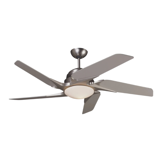
Solo Ceiling Fans
SO52
Installation Instructions
Model: SO52
®
BETTER BY DESIGN
Advertisement
Table of Contents

Related Manuals for Craftmade Solo SO52


Summary of Contents for Craftmade Solo SO52
- Page 1 650 S. Royal Lane, Suite 100 Coppell, TX 75019 EE.UU. (800) 486- 4892 8:00 a 5:00 CST (Hora local central) Número de fax sin cargo: (877) 304-1728 Correo electrónico: customerservice@craftmade.com www. craftmade.com ® UNE CONCEPTION EXCEPTIONNELLE P. O. Box 1037 650 S.
-
Page 2: What You Have
For safety and best operating results, we recommend that you have a qualified electrician assemble and install your fan. WARNING: To reduce the risk of fire or electric shock, do not use this fan with any solid state speed control device. - Page 3 Preparation Important: When using an existing outlet box, be sure the box is securely attached to the building structure and can support the full weight of the fan. Failure to do so can result in serious injury or death. Step 1 Turn off circuit breakers and wall switch to the fan supply line leads.
- Page 4 "acceptable for fan support" and use mounting screws provided with the outlet box. Most outlet boxes commonly used for the support of lighting fixtures are not acceptable for fan support and may need to be replaced. Consult a qualified electrician if in doubt.
- Page 5 Step 8 1. Connect fan wires to ceiling wires: white fan wire to white outlet wire, black to black and green to green. Wire connectors (S6) are provided for your convenience. If an additional blue wire is present then also connect the blue wire to the black wire.
- Page 6 Step 11 For blade assembly, position blade (7) through slot in fan motor housing so that all screw holes are aligned (as shown in figure below). Position light house assembly so that the top screw hole in blade lines up with housing slot in flywheel.
- Page 7 The switches are located on the back of the remote control unit and in the top motor housing of the fan on the receiving module. The switches can be set in any position as long as both the wall unit and receiving module switches are set the same.
-
Page 8: Electrical Connections
For optional wall control see figure B or Figure C for alternate wiring. When wall switches are employed, switches should be UL listed for use with ceiling fan. NOTE: Make sure fan on/off switch is always at "high speed" location if your fan is controlled by additional wall switch. Ground... -
Page 9: Common Problems
3. Check the weight of blades. All our blades are weighed on electronic scales. The weight is marked on the reverse side of the fan blade near the motor end. All of the blades should be the same weight to prevent fan from wobbling. -
Page 10: Componentes Incluidos
7. Para aminorar el riesgo de un incendio, choque eléctrico o lesión personal, móntelo a una caja de salida adecuada para soportar el ventilador ("Acceptable for Fan Support") y utilice los tornillos de montaje incluidos con la caja de salida. - Page 11 Paso 2 Determine el método de montaje a usar. A. Montaje con vara hacia abajo B. Montaje angular Pieza Craftmade 45AD (consulte al distribuidor) IMPORTANTE: Si utiliza el método de montaje angular, revise que el ángulo del cielo raso no supere los 35 .
- Page 12 Cable negro de la antena ADVERTENCIA: Móntelo en la caja de salida marcada “acceptable for fan support” (aceptable como soporte del ventilador) con los tornillos suministrados con la caja para reducir el riesgo de incendio o lesiones personales. La mayoría de las cajas de salida de uso común para el soporte de portalámparas no son aceptables para el soporte del...
- Page 13 Paso 8 1. Conecte los cables del ventilador a los del techo: el cable blanco del ventilador con el cable blanco de salida, negro con negro y verde con verde. Se incluyen los conectores de cables (S6) para su conveniencia. Si hay un cable azul adicional, conéctelo también con el cable negro.
- Page 14 Paso 11 Para ensamblar las aspas, coloque cada aspa (7) en un aposición tal que atraviese la ranura localizada en la cubierta del motor del ventilador de tal manera que todos los orificios para los tornillos estén alineados, como se muestra en la ilustración de abajo.
-
Page 15: Instrucciones De Uso
Ajuste de los interruptores de frecuencia Un conjunto de interruptores de frecuencia preajustados de fábrica operan la unidad remota del control. Los interruptores están situados a la espalda de la unidad remota del control y en la cubierta superior del motor del ventilador sobre el módulo receptor. -
Page 16: Conexiones Eléctricas
Conexiones eléctricas Conecte los cables negros del ventilador al cable negro de salida. Conecte el cable blanco del ventilador al cable blanco de salida y al cable conductor a tierra verde desde el conductor a tierra al circuito de suministro (consulte la figura A). Utilice los conectores de cable suministrados con el ventilador. -
Page 17: Problemas Comunes
4. Se adjunta un paquete de balanceo, si es necesario. Peso: El peso del ventilador completo, incluido el herraje de montaje es de 24 lbs. (10.9 kg). Ventilateurs de plafond SO52 Instructions d’installation Modèle : SO52 Solo ® UNE CONCEPTION EXCEPTIONNELLE... -
Page 18: Composants Inclus
S3. Vis et rondelles des supports S4. Vis des pales S5. Vis du moteur S6. Connecteurs de fils S7. Boulon et écrou de sécurité S8. Crochet en « J » S9. Bride 4. Pince à dénuder Composants inclus Quantité FAN OFF HIGH Quantité... - Page 19 A. Montage à l’aide d’une tige de Montage à l’aide d’une tige de suspension suspension B. Montage sur une surface inclinée Pièce Craftmade n 45AD (consultez votre revendeur) IMPORTANT: si vous utilisez la méthode de montage inclinée, vérifiez que l'angle du plafond est inférieur à...
- Page 20 « acceptable for fan support » (prise en charge de ventilateur) et utilisez les vis de montage fournies avec la boîte de sortie. La plupart des boîtes de sortie utilisées avec les dispositifs d'éclairage ne prennent pas en charge les ventilateurs et doivent être éventuellement...
- Page 21 Étape 8 1. Connectez les fils du ventilateur à ceux du plafond : le fil de ventilateur blanc au fil de sortie blanc, le fil noir au fil noir et le fil vert au fil vert. Les connecteurs (S6) sont fournis au cas où vous en auriez besoin. S'il existe un fil bleu supplémentaire, connectez-le au fil noir.
- Page 22 Étape 11 Pour assembler la pale, placez cette dernière (7) dans la fente du boîtier du moteur de ventilateur, de manière à ce que tous les trous de vis soient alignés (comme le montre le schéma ci-dessous). Placez le dispositif d'éclairage de manière à...
- Page 23 1 2 3 4 1 2 3 4 PUSH Couvercle du boîtier HIGH MEDIUM REVERSE FAN OFF Télécommande REMARQUE : Borne de la pile Boîtier de la télécommande Mode d’emploi Ces commandes permettent de contrôler la vitesse du moteur du ventilateur.
-
Page 24: Connexions Électriques
Connexions électriques Branchez les fils bleu et noir du ventilateur (s’ils sont fournis) sur le fil noir de la boîte de sortie. Connectez le fil blanc du ventilateur au fil blanc de la boîte de sortie et connectez le fil de terre vert sortant du conducteur de mise à la terre au circuit d'alimentation (voir la figure A).
Need help?
Do you have a question about the Solo SO52 and is the answer not in the manual?
Questions and answers
I'm looking for a replacement remote control for Craftmade Solo fan model s052,ar52, Are they available or is there a generic one available?