Table of Contents
Advertisement
Quick Links
Maintenance Manual
™
VectorStar
MN469xC Series
Multiport Test Set
VectorStar MN4694C, K Connectors, for the MS4642A/B or MS4644A/B VNA
VectorStar MN4697C, V Connectors, for the MS4645A/B or MS4647A/B VNA
Anritsu Company
Part Number: 10410-00730
490 Jarvis Drive
Revision: D
Morgan Hill, CA 95037-2809
Published: August 2021
USA
Copyright August 2021 Anritsu Company
http://www.anritsu.com
Advertisement
Table of Contents
Troubleshooting

Related Manuals for Anritsu VectorStar MN469 C Series


Summary of Contents for Anritsu VectorStar MN469 C Series
- Page 1 VectorStar MN4694C, K Connectors, for the MS4642A/B or MS4644A/B VNA VectorStar MN4697C, V Connectors, for the MS4645A/B or MS4647A/B VNA Anritsu Company Part Number: 10410-00730 490 Jarvis Drive Revision: D Morgan Hill, CA 95037-2809 Published: August 2021 Copyright August 2021 Anritsu Company http://www.anritsu.com...
-
Page 3: Table Of Contents
Contacting Anritsu ........ - Page 4 Table of Contents (Continued) Directivity and Test Port Match Verification ........3-7 Equipment Required for VNA System with MN4694C.
- Page 5 Table of Contents (Continued) 5-10 Low Band Bridge ............5-13 A20, A21 Replacement .
- Page 6 Table of Contents (Continued) Contents-4 PN: 10410-00730 Rev. D MN469xC Series Multiport Test Set MM...
-
Page 7: Chapter 1-General Information
From here, you can select the latest sales, service and support contact information in your country or region, provide online feedback, complete a "Talk to Anritsu" form to get your questions answered, or obtain other services offered by Anritsu. -
Page 8: Related Manuals And Documentation
1-4 Related Manuals and Documentation Chapter 1 — General Information Related Manuals and Documentation All documents listed in this section are available on the VectorStar User Documentation USB Memory Device 2300-564-R, except for the Calibration, Verification, and System Performance Verification documents, which are included on a separate USB memory device included in each kit. -
Page 9: Vectorstar Mn469Xc Series Multiport Vna Measurement System
Chapter 1 — General Information 1-4 Related Manuals and Documentation • ME7838E4/E4X Modular BB/mmWave Quick Start Guide (QSG) – 10410-00771 • ME7838x4 Series Modular BB/mmWave Installation Guide (IG) – 10410-00734 • ME7838x4 Series Modular BB/mmWave Maintenance Manual (MM) – 10410-000736 VectorStar MN469xC Series Multiport VNA Measurement System •... -
Page 10: Vectorstar Multiport Vna System Overview
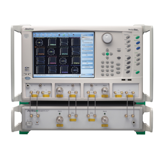
Figure 1-1. Overall Block Diagram of the VectorStar Multiport VNA System The Anritsu MN469xC Series Multiport Test Set provides multiple test port capabilities for the Anritsu VectorStar MS464xB/MS464xA Series Vector Network Analyzer. The MN469xC Series Test Set contains a switch matrix and switch matrix controller that facilitates multiple test port connections to the device under test. -
Page 11: Mn469Xc Multiport Test Set Functional Description
Chapter 1 — General Information 1-6 MN469xC Multiport Test Set Functional Description MN469xC Multiport Test Set Functional Description A block diagram of the MN469xC Series Multiport Test Set is shown in Figure 1-2. (REAR PANEL) To VNA To VNA Pt 1 Src Pt 1 Src Pt 2 Src Port 2 Source... -
Page 12: Low Band Operation 70 Khz To 2.5 Ghz
1-6 MN469xC Multiport Test Set Functional Description Chapter 1 — General Information The MN469xC test set contains eight SPDT RF switches. Four switches, A4, A5, A6 and A7, operate in low band frequencies below 2.5 GHz. Four switches, A12, A13, A18 and A19, operate in high band frequencies from 2.5 GHz and beyond. -
Page 13: Electrostatic Discharge (Esd) Prevention
Chapter 1 — General Information 1-7 Electrostatic Discharge (ESD) Prevention Electrostatic Discharge (ESD) Prevention All electronic devices, components, and instruments can be damaged by electrostatic discharge. It is important to take preventive measures to protect the instrument and its internal subassemblies from electrostatic discharge. -
Page 14: Recommended Test Equipment
Type: K male to K female MN4694C Adapter (Qty 2) Air Line Connector Type: K female Anritsu Model SC7760 MN4694C Return Loss: 20 dB Anritsu Model SC4808 or MN4694C Offset Termination Connector Type: K female SC7888 Calibration Kit Connector Type: V Anritsu Model 3654D MN4697C... - Page 15 Model – Test Software Anritsu 2300-531-R All Models 5/16” (8 mm) Torque End Wrench, Anritsu 01-201, use with 01-204 All Models Torque Wrench set to 8 lbf ꞏ in (0.9 N ꞏ m) below. 1/2” (12.7 mm) Torque End Wrench,...
- Page 16 1-8 Recommended Test Equipment Chapter 1 — General Information 1-10 PN: 10410-00730 Rev. D MN469xC Series Multiport Test Set MM...
-
Page 17: Introduction
This chapter provides replaceable parts information for MN469xC Series Multiport Test Sets. Exchange Assembly Program Anritsu maintains a module exchange program for selected subassemblies. If a malfunction occurs in one of these sub-assemblies, the defective item can be exchanged. Upon receiving your request, Anritsu will ship the exchange subassembly to you. - Page 18 2-3 Replaceable Parts Chapter 2 — Replaceable Parts Table 2-1. Replaceable Parts List (2 of 3) Part Number Part Description – Drawing “A” Number 3-64016<R> Low Band Bridge – A20, A21 All Models; RoHS compliant ND70079<R> Low Band Switch – A4, A5, A6, A7 All Models;...
- Page 19 Chapter 2 — Replaceable Parts 2-3 Replaceable Parts Table 2-1. Replaceable Parts List (3 of 3) Part Number Part Description – Drawing “A” Number 3-62112-81 RF Cable, SMA Connector, VNA Src to Test Set Src, Rear Panel All Models; RoHS compliant ND71327 Fan Assembly, Rear Panel All Models;...
- Page 20 2-3 Replaceable Parts Chapter 2 — Replaceable Parts Fan Assembly Power Supply Control PCB GPIB PCB Table 2-1, “Replaceable Parts List” on page 2-1 for identification of Replacement Part Numbers. Item Description Item Description Power Supply Diplexer/Bias-Tee Cooling Fan Assembly High Band SPDT Switch Control PCB Assembly High Band SPDT Switch...
-
Page 21: Chapter 3-Performance Verification
While there are many ways of verifying VNA performance, sometimes simpler procedures are desired. The use of a verification kit, available from Anritsu, is a simpler method of verifying the measurement capabilities of the instrument by analyzing the measurement of artifacts that are traceable to national standards laboratories. -
Page 22: Traceability And Uncertainty
3-2 Traceability and Uncertainty Chapter 3 — Performance Verification Traceability and Uncertainty Vector network analyzers (VNAs) are precision instruments for making high frequency and broadband measurements in devices, components, and instrumentations. The accuracy of these measurements is affirmed by demonstrated and adequate traceability of measurement standards. Metrological traceability, per International vocabulary of metrology, JCGM 200:2008, is property of a measurement result whereby the result can be related to a reference through a documented unbroken chain of calibrations, each contributing to the measurement uncertainty. -
Page 23: Electrostatic Discharge Prevention
Chapter 3 — Performance Verification 3-3 Electrostatic Discharge Prevention Electrostatic Discharge Prevention All electronic devices, components, and instruments can be damaged by electrostatic discharge. Thus, it is important to take preventative measures to protect the instrument from damage caused by electrostatic discharge. -
Page 24: S-Parameters Measurements Verification
(characterization) data for those devices that was obtained using the Factory Standard MS464XX Vector Network Analyzer (at Anritsu). The Factory Standard MS464XX system is traceable to NIST through the impedance Standards of the Anritsu Calibration laboratory. These standards are traceable to NIST through precision mechanical measurements, NIST-approved microwave theory impedance derivation methods, and electrical impedance comparison measurements. -
Page 25: Equipment Required
• The pin depths of all connectors and the proper torquing of connections. These same factors also affect the VNA measurement quality. Consult the reference manual supplied with Anritsu Calibration Kits and Verification Kits for proper use, care, and maintenance of the devices contained in these kits. -
Page 26: Special Precautions
3-5 S-Parameters Measurements Verification Chapter 3 — Performance Verification Special Precautions When performing the procedures, observe the following precautions: • Minimize vibration and movement of the system, attached components, and test cable. • Clean and check the pin depth and condition of all adapters, test port cables, calibration components, and impedance transfer standards. -
Page 27: Directivity And Test Port Match Verification
Equipment Required for VNA System with MN4694C • Calibration Kit, K Connector, Anritsu Model 3652A • Phase Equal Adapter, K(m) to K(f) Anritsu Model 33KKF50B (Qty 2; in addition to the two adapters in 3652A) • Air Line, K Connector, Anritsu Model SC7760 •... - Page 28 3-6 Directivity and Test Port Match Verification Chapter 3 — Performance Verification Table 3-2. VectorStar VNA Segmented Sweep Setup for VNA System with MN4694C Test Set # of Pts IFBW P1 Src Pwr P2 Src Pwr 5 dBm 5 dBm 70 kHz 200 kHz 10 Hz...
- Page 29 Chapter 3 — Performance Verification 3-6 Directivity and Test Port Match Verification 28. Select Response | Tr2 | S22 29. Select Tr3 | More Single Mode | S33 30. Select Tr4 | More Single Mode | S44 31. Insert the Calibration Kit Components Coefficients USB Memory Stick into one of the front panel USB ports.
- Page 30 3-6 Directivity and Test Port Match Verification Chapter 3 — Performance Verification 37. Change all DUT Connector settings to K-Conn(F) for MN4694C or V-Conn(F) for MN4697C in the One Port Cal Setup dialog box. Click the OK button when done. See Figure 3-3 below.
- Page 31 Chapter 3 — Performance Verification 3-6 Directivity and Test Port Match Verification 38. Select Back to return to the One Port Cal/s Menu. See Figure 3-4 below. Figure 3-4. One Port Cal/s Menu MN469xC Series Multiport Test Set MM PN: 10410-00730 Rev. D 3-11...
- Page 32 40. Connect the Open from the Calibration Kit to Port 1 of the VNA. Use the Anritsu 01-201 torque wrench from the Anritsu 365xx Calibration Kit to tighten the connection to improve the quality of the calibration. Do the same for other calibration standards Note (e.g.
- Page 33 Chapter 3 — Performance Verification 3-6 Directivity and Test Port Match Verification 47. Select Port 2 Reflective Device 48. Connect the Open from the Calibration Kit to Port 2 of the VNA. 49. Select Open. 50. Disconnect the Open from Port 2 and connect the Short. 51.
- Page 34 3-6 Directivity and Test Port Match Verification Chapter 3 — Performance Verification Figure 3-6. Log Mag Display 78. Position Mkr 2 to the bottom of the trough (or to the top of the peak if the ripple has the greatest position peak.) 79.
- Page 35 Chapter 3 — Performance Verification 3-6 Directivity and Test Port Match Verification 82. Also find the corresponding Ref + X or Ref X value from the RF measurement chart. Figure 3-7. RF Measurement Chart 83. Use the following formula to calculate the directivity: MN469xC Series Multiport Test Set MM PN: 10410-00730 Rev.
- Page 36 3-6 Directivity and Test Port Match Verification Chapter 3 — Performance Verification • For ripple with a negative trough: Directivity = Return Loss value |Mkr 2 value| |Ref X value| • For ripple with a positive peak: Directivity = Return Loss value ...
-
Page 37: Test Port Power Verification
Port Power level. Refer to the VectorStar MS4640A/B Series VNA 2300-531-R System Verification Software Quick Start Guide - 10410-00291, for details about running the software. Equipment Required • Power Meter, Anritsu Model ML2437A or ML2438A • Power Sensor, Anritsu Model SC7770 • Adapter, N male to V female, Pasternack Model PE9720 •... -
Page 38: Noise Floor Verification
3-8 Noise Floor Verification Chapter 3 — Performance Verification Noise Floor Verification This test verifies the noise floor performance of the VectorStar Multiport VNA system at the test port of the MN469xC. The Noise Floor test procedures are automated by using the VectorStar MS4640A/B Instrument Test Software, CDROM part number 2300-531-R. -
Page 39: Chapter 4-Troubleshooting
Chapter 4 — Troubleshooting Introduction This chapter provides information about troubleshooting tests that can be used to check the MN469xC Multiport Test Set for proper operation. These tests are intended to be used as a troubleshooting tool for checking the functionality of the components and sub-assemblies in the test set. General Safety Warnings Many of the troubleshooting procedures presented in this chapter require the removal of instrument covers to gain access to subassemblies and modules. -
Page 40: Troubleshooting Test Set Fails To Power Up
4-4 Troubleshooting Test Set Fails to Power Up Chapter 4 — Troubleshooting Troubleshooting Test Set Fails to Power Up If the MN469xC test set fails to power up when connected to an AC power source and the Power key is pressed, perform the power supply checks described below. - Page 41 4-4 Troubleshooting Test Set Fails to Power Up Chapter 4 — Troubleshooting Figure 4-1. 4-Port Test Set Control PCB P4 Connector Location MN469xC Series Multiport Test Set MM PN: 10410-00730 Rev. D...
-
Page 42: Troubleshooting Rf Switch Functional Check
Note switches. Equipment Required for VNA System with MN4694C • Anritsu Model 3652A K Connector Calibration Kit (For MN4694C) • Anritsu Model 3670K50-2 K Connector Through Cable (For MN4694C) Equipment Required for VNA System with MN4697C • Anritsu Model 3654D V Connector Calibration Kit (For MN4697C) •... -
Page 43: Troubleshooting Directivity And Test Port Match Failure
Equipment Required for VNA System with MN4694C • Calibration Kit, K Connector, Anritsu Model 3652A • Phase Equal Adapter, K(m) to K(f) Anritsu Model 33KKF50B (Qty 2) • Air Line, K Connector, Anritsu Model T2023-2 • 20 dB Offset Termination, K(f) Connector, Anritsu Model SC4808 Equipment Required for VNA System with MN4697C •... - Page 44 4-6 Troubleshooting Directivity and Test Port Match Failure Chapter 4 — Troubleshooting PN: 10410-00730 Rev. D MN469xC Series Multiport Test Set MM...
-
Page 45: Chapter 5-Component Replacement
• Either a #1 or #2 size Phillips screwdriver • 5/16 inch open end wrench • Anritsu 01-201 (8 lbfꞏin) 5/16 inch torque wrench. Always use a torque wrench calibrated to 8 lbfꞏin when tightening the RF connectors on semi-rigid Caution RF cables. -
Page 46: Removing The Covers
5-3 Removing the Covers Chapter 5 — Component Replacement Removing the Covers 1. Switch the VectorStar VNA and the MN469xC Test Set power off and remove the power cords. 2. Remove the MN469xC Test Set from the VectorStar VNA by disconnecting all cable connections and separating the test set from the VectorStar VNA. -
Page 47: Location Of Major Components And Sub-Assemblies
Chapter 5 — Component Replacement 5-4 Location of Major Components and Sub-assemblies Location of Major Components and Sub-assemblies Figure 5-2 below shows the location of major components and sub-assemblies in the MN469xC Series Multiport Test Set. Table 2-1, “Replaceable Parts List” on page 2-1 for identification of Engineering “A”... -
Page 48: Gpib-Parallel Interface Pcb Replacement
5-5 GPIB-Parallel Interface PCB Replacement Chapter 5 — Component Replacement GPIB-Parallel Interface PCB Replacement Assemblies: 2000-989 or 3-2000-989 This section provides a procedure for removing and replacing the GPIB-Parallel Interface PCB Assembly in the test set. 1. Remove the top cover from the test set. Refer to Section 5-3 “Removing the Covers”... -
Page 49: Rear Gpib Connector Pcb Replacement
Chapter 5 — Component Replacement 5-6 Rear GPIB Connector PCB Replacement Rear GPIB Connector PCB Replacement Assemblies: 2000-989 or 3-2000-989 This section provides a procedure for removing and replacing the Rear Panel GPIB Connector PCB in the test set. The Rear Panel GPIB Connector PCB Assembly is a part of the GPIB-Parallel Interface PCB Note Assembly Replacement Kit, part number 2000-989. - Page 50 5-6 Rear GPIB Connector PCB Replacement Chapter 5 — Component Replacement JUMPER # 2 JUMPER # 1 1. Jumper # 1 goes from pin 12 of the GPIB connector to pin 13 of the GPIB connector. 2. Jumper # 2 goes from pin 12 of the GPIB connector to pin 1 of the Dip Switch connector Figure 5-5.
-
Page 51: Control Pcb Assembly Replacement
Chapter 5 — Component Replacement 5-7 Control PCB Assembly Replacement Control PCB Assembly Replacement Assemblies: ND70927<R> or 3-ND70927<R> This section provides a procedure for removing and replacing the 4-Port Test Set Control PCB in the test set. 1. Remove the top cover from the test set. Refer to Section 5-3 “Removing the Covers”... -
Page 52: Power Supply Replacement
5-8 Power Supply Replacement Chapter 5 — Component Replacement Power Supply Replacement Assemblies: 3-40-183 1. Remove the top cover and left cover from the test set. Refer to Section 5-3. 2. Remove the board as illustrated in Figure 5-7. 1. At the rear of the power supply, disconnect the 3 Pin 4. -
Page 53: Low Band Switch
2. Replace the A4 module as illustrated in Figure 5-8. Note Use Anritsu 01-201 Torque Wrench to tighten all RF connectors when installing the module. See Note 1. Disconnect the RF cable from the J1 connector of the 3. Disconnect the two connectors from J2 and J3 A4 module and the Rear Panel. -
Page 54: A5 Replacement
Figure 5-9. Note Use Anritsu 01-201 Torque Wrench to tighten all RF connectors when installing the module. 1. Disconnect the RF cable from the J1 connector of the 3. Disconnect the two connectors from J2 and J3 A5 module and carefully lift it out of the way. -
Page 55: A6 Replacement
Figure 5-10. Note Use Anritsu 01-201 Torque Wrench to tighten all RF connectors when installing the module. 1. Disconnect the RF cable from the J1 connector of the 3. Disconnect the two RF cables from J2 and J3 A6 module and the Rear Panel. -
Page 56: A7 Replacement
Figure 5-11. Note Use Anritsu 01-201 Torque Wrench to tighten all RF connectors when installing the module. See Note 1. Disconnect the RF cable from the J1 connector of the 3. Disconnect the two RF cables from J2 and J3 A7 module and the Rear Panel. -
Page 57: Low Band Bridge
2. Replace the A20 or A21 module as illustrated in Figure 5-12. Note Use Anritsu 01-201 Torque Wrench to tighten all RF connectors when installing the module. See Note 1. Remove the A4 low band switch. See “A4 3. Remove the A20/A21 assembly Replacement”... -
Page 58: High Band Spdt Switch Control Pcb Assembly
5-11 High Band SPDT Switch Control PCB Assembly Chapter 5 — Component Replacement 5-11 High Band SPDT Switch Control PCB Assembly Assembly: ND70926<R> or 3-ND70926<R> This section provides a procedure for removing and replacing the High Band SPDT Switch Control PCB Assembly. -
Page 59: 5-12 High Band Spdt Switch Assembly
Figure 5-2 on page 5-3 for module locations. A12 Replacement Note Use Anritsu 01-201 Torque Wrench to tighten all RF connectors when installing the module. 1. Remove the top cover from the test set as instructed in Section 5-3. 2. Replace the Switch Assembly as illustrated in Figure 5-14. -
Page 60: A13 Replacement
For this procedure, a right angle wrench is required to loosen the RF cable connectors attached at Note the front panel. Use Anritsu 01-201 Torque Wrench to tighten all RF connectors when installing the module. 1. Remove the top cover from the test set as instructed in Section 5-3. -
Page 61: A18 Replacement
2. Replace the Switch Assembly as illustrated in Figure 5-16 Note Use Anritsu 01-201 Torque Wrench to tighten all RF connectors when installing the module. 1. Remove Switch Control Board and the 3 standoffs from the switch per the procedure in Section 5-11, then disconnect the cables from J2 and J3 of the switch and gently move them clear of the connectors. -
Page 62: A19 Replacement
For this procedure, a right angle wrench is required to loosen the RF cable connectors attached at Note the front panel. Use Anritsu 01-201 Torque Wrench to tighten all RF connectors when installing the module. 1. Remove the top cover from the test set as instructed in Section 5-3. -
Page 63: 5-13 Diplexer Assembly
This section provides a procedure for removing and replacing the two Diplexer Assemblies A8, and A10. Refer Figure 5-2, “Location of Major Components and Subassemblies” on page 5-3. The DC bias leads must be desoldered from the module prior to removal. Use Anritsu 01-201 Torque Note Wrench to tighten all RF connectors when installing the module. -
Page 64: A10 Replacement
1. Remove the top cover from the test set as instructed in Section 5-3. The DC bias leads must be desoldered from the module prior to removal. Use Anritsu 01-201 Torque Note Wrench to tighten all RF connectors when installing the module. -
Page 65: 5-14 Test Port Connector Replacement
Chapter 5 — Component Replacement 5-14 Test Port Connector Replacement 5-14 Test Port Connector Replacement Assemblies: 34YK50C or 34YV50C This section provides instructions for removing and replacing the Test Port Connectors. 1. Loosen and remove the Test Port Connector using a 1/2” torque wrench. 2. -
Page 66: 5-15 Port Coupler
2. Remove the A8 Diplexer Assembly as instructed in Section 5-13. De-soldering of the DC Bias wires from the A8 Diplexer Assembly is not required. Use Anritsu Note 01-201 Torque Wrench to tighten all RF connectors when installing the module. -
Page 67: A15 Replacement
2. Remove the A10 Diplexer Assembly as instructed in Section 5-13. De-soldering of the DC Bias wires from the A10 Diplexer Assembly is not required. Use Anritsu Note 01-201 Torque Wrench to tighten all RF connectors when installing the module. -
Page 68: 5-16 Fan Assembly Replacement
5-16 Fan Assembly Replacement Chapter 5 — Component Replacement 5-16 Fan Assembly Replacement Assembly: ND71327 or 3-ND83592 This section provides a procedure for removing and replacing the rear panel fan assembly in the test set. 1. Remove the top cover from the test set as instructed in Section 5-3. -
Page 69: Appendix A-Test Records
This appendix provides test records that can be used to record the performance of MN469xC in conjunction with a 2-Port VectorStar VNA. As the MN469xC Series Test Set provides multiple test port capabilities for the Anritsu VectorStar MS464xA/B Series Vector Network Analyzer, they do not have any performance specifications separate from the VectorStar VNA. -
Page 70: Mn4694C Multiport Vna System Test Record
A-2 MN4694C Multiport VNA System Test Record Appendix A — Test Records MN4694C Multiport VNA System Test Record Instrument Information for MN4694C MN4694C Serial Number: Operator: Date: VectorStar VNA Model: VectorStar VNA Serial Number: VectorStar VNA Options: MS4642A [ ] MS4644A [ ] MS4642B [ ] MS4644B [ ] System Performance can be verified either by using Verification Kit to perform S-Parameters Measurements Verification using Verification Kit or using airline to perform verification of system... -
Page 71: Test Port Match For Mn4694C Vna System
Appendix A — Test Records A-2 MN4694C Multiport VNA System Test Record Test Port Match for MN4694C VNA System Table A-2. Test Port Match Record for MN4694C Multiport VNA System Port 1 (VNA) Port 2 (VNA) Port 3 (Test Set) Port 4 (Test Set) Measured Measured... -
Page 72: Mn4697C Multiport Vna System Test Record
A-3 MN4697C Multiport VNA System Test Record Appendix A — Test Records MN4697C Multiport VNA System Test Record Instrument Information for MN4697C MN4697C Serial Number: Operator: Date: VectorStar VNA Model: VectorStar VNA Serial Number: VectorStar VNA Options: MS4645A [ ] MS4647A [ ] MS4645B [ ] MS4647B [ ] System Performance can be verified either by using Verification Kit to perform S-Parameters Measurements Verification using Verification Kit or using airline to perform verification of system... -
Page 73: Test Port Match For Mn4697C
Appendix A — Test Records A-3 MN4697C Multiport VNA System Test Record Test Port Match for MN4697C Table A-4. Test Port Match Record for MN4697C Multiport VNA System Port 1 (VNA) Port 2 (VNA) Port 3 (Test Set) Port 4 (Test Set) Measured Measured Measured... - Page 74 A-3 MN4697C Multiport VNA System Test Record Appendix A — Test Records PN: 10410-00730 Rev. D MN469xC Series Multiport Test Set MM...
-
Page 75: Appendix B-Specifications
• VectorStar MS4640B Series VNA Technical Data Sheet – 11410-00611 • VectorStar MN469xC Series Multiport Test Set Technical Data Sheet – 11410-00777 Updated product information can be found on your product page: https://www.anritsu.com/en-us/test-measurement/products/ms4640b-series MN469xC Series Multiport Test Set MM PN: 10410-00730 Rev. D... - Page 76 B-1 Technical Data Sheet Appendix B — Specifications PN: 10410-00730 Rev. D MN469xC Series Multiport Test Set MM...
- Page 78 Anritsu Company 490 Jarvis Drive Anritsu utilizes recycled paper and environmentally conscious inks and toner. Morgan Hill, CA 95037-2809 http://www.anritsu.com...
Need help?
Do you have a question about the VectorStar MN469 C Series and is the answer not in the manual?
Questions and answers