Table of Contents
Advertisement
Quick Links
Installation Guide
™
VectorStar
MN469xC Series
Multiport Test Set
VectorStar MN4694C, K Connectors, for the MS4642A/B or MS4644A/B VNA
VectorStar MN4697C, V Connectors, for the MS4645A/B or MS4647A/B VNA
Anritsu Company
Part Number: 10410-00737
490 Jarvis Drive
Revision: C
Morgan Hill, CA 95037-2809
Published: June 2017
USA
Copyright 2017 Anritsu Company
http://www.anritsu.com
Advertisement
Table of Contents
Troubleshooting

Related Manuals for Anritsu MN469xC Series


Summary of Contents for Anritsu MN469xC Series
- Page 1 VectorStar MN4694C, K Connectors, for the MS4642A/B or MS4644A/B VNA VectorStar MN4697C, V Connectors, for the MS4645A/B or MS4647A/B VNA Anritsu Company Part Number: 10410-00737 490 Jarvis Drive Revision: C Morgan Hill, CA 95037-2809 Published: June 2017 Copyright 2017 Anritsu Company http://www.anritsu.com...
-
Page 3: Table Of Contents
VectorStar™ ME7838A4 Multiport BB/mm-Wave VNA Measurement System ..1-4 VectorStar MN469xC Series Multiport VNA Measurement System ....1-5 Calibration, Verification, and System Performance Verification . - Page 4 Table of Contents (Continued) Preparation for Shipment ........... . . 4-5 Use a Suitable Container.
-
Page 5: Chapter 1-General Information
• MN4697C, V Connectors, for the VectorStar MS4645A/B or MS4647A/B VNAs Throughout this manual, the term test set is used to refer to the MN469xC Series Multiport Test Set, the term VNA is used to refer to the VectorStar MS464xA/B Series Vector Network Analyzer, and the term DUT is used to refer to the device under test. -
Page 6: Test Set Components
1-3 Test Set Components General Information Test Set Components The MN469xC Series Multiport Test Set comes with the following components. Table 1-1. MN469xC Multiport Test Set Components and Cables Part Numbers Description Connection From Connection To VNA port labeled: MN469xC port labeled:... -
Page 7: Functional Description
General Information 1-4 Functional Description Functional Description The functional description is based on the functional block diagram of the MN469xC Series Test Set shown below (Figure 1-2). The VectorStar VNA sends switch control commands via the GPIB bus to the GPIB to Parallel Digital Interface PCB in the test set. -
Page 8: Technical Specifications
1-5 Technical Specifications General Information Technical Specifications For complete technical specifications, refer to the VectorStar MN469xC Series Multiport Technical Data Sheet – 11410-00777. Related Documentation All documents listed in this section are available on the VectorStar ™ User Documentation USB Memory Device 10920-00067, except for the Calibration, Verification, and System Performance Verification documents, which are included on a separate USB memory device included in each kit. -
Page 9: Vectorstar Mn469Xc Series Multiport Vna Measurement System
From here, you can select the latest sales, service and support contact information in your country or region, provide online feedback, complete a "Talk to Anritsu" form to get your questions answered, or obtain other services offered by Anritsu. - Page 10 1-7 Contacting Anritsu General Information PN: 10410-00737 Rev. C MN469xC Multiport Test Set IG...
-
Page 11: Chapter 2-Hardware Installation
If the shipment is incomplete or if the test set is damaged mechanically or electrically, notify your local sales representative or Anritsu Customer Service. If either the shipping container is damaged or the cushioning material shows signs of stress, notify the carrier as well as Anritsu. Keep the shipping materials for the carrier's inspection. -
Page 12: System Connections
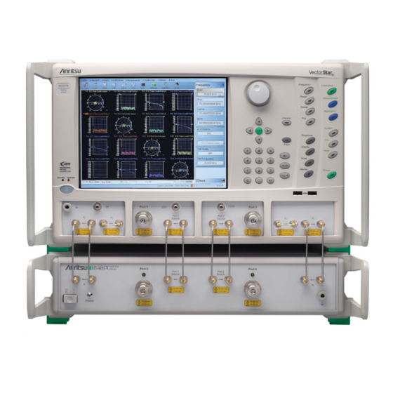
2-5 System Connections Hardware Installation System Connections The figure below shows the front panel connections between the Test Set and VNA. Make the semi-rigid cable connections as shown in Figure 2-1, Figure 2-2, and in Table 2-1. Before installing the test set in its operating environment, ensure that the airflow hole pattern at the Note right side of the instrument is clear. -
Page 13: Rear Panel Connections
Hardware Installation 2-5 System Connections Rear Panel Connections 1. Connect the GPIB cable between the VNA Rear Panel Dedicated GPIB connector and the Test Set IEEE 488.2 GPIB connector as shown in Figure 2-2. 2. On the VNA rear panel, remove and set aside the eight SMA (m-m) loops. 3. - Page 14 2-5 System Connections Hardware Installation Table 2-1. MN469xC Multiport semi-rigid Cable Interconnect Part Numbers and Locations Index Part Numbers Description/Torque Connection From Connection To Front Panel Connections VNA port labeled: MN469xC port labeled: b1 (In) b1 (In) VNA port labeled: MN469xC port labeled: b1 (Out) b1 (Out)
- Page 15 Hardware Installation 2-5 System Connections Table 2-1. MN469xC Multiport semi-rigid Cable Interconnect Part Numbers and Locations Index Part Numbers Description/Torque Connection From Connection To SMA male-male semi-rigid MN469xC port labeled: MS464xB port labeled: Tighten using an 8 mm (5/16 in) 3-62112-81 TO VNA Port 1 Src torque end wrench set to 0.9 N·m...
-
Page 16: Rear Panel Dip Switch Gpib Address Setting
Rear Panel DIP Switch GPIB Address Setting The MN469xC Series Test Set GPIB address must match the GPIB address set on the VNA and is set on the Test Set by rear panel DIP switches. The factory default GPIB address is 16 (Switch 1 ON and all other switches OFF). -
Page 17: Changing Vna Addresses For The Test Set
Changing VNA Addresses for the Test Set The default VNA GPIB address for the MN469xC Series Test Set is GPIB 16 and must match the address set on the Test Set through the rear panel DIP switches. To change the GPIB address on the VNA, navigate to the REMOTE INTER menu. -
Page 18: Power Up Sequence
2-7 Power Up Sequence Hardware Installation Power Up Sequence The VNA application must be started after the Test Set is connected and powered up. If the VNA application is started before the Test Set, the VNA will remain in 2-port mode and the 4-port functions Note will not be available. -
Page 19: Chapter 3-Initial System Checkout
Chapter 3 — Initial System Checkout Introduction This chapter provides the general initial system checkout for a completely assembled multiport system. Once this procedure is complete, the system is ready for calibration and available to make measurements up to a 4-port configuration. - Page 20 3-3 MN469xC Multiport Test Set Configuration Verification Initial System Checkout 7. Select Trace 3 and repeat Step 3 setting Numerator = B1, Denominator = 1, Driver Port = 1. 8. Select Trace 4 and repeat Step 3, setting Numerator = A2, Denominator = 1, Driver Port = 2. 9.
- Page 21 Initial System Checkout 3-3 MN469xC Multiport Test Set Configuration Verification 13. Select Trace 4 and repeat Step 8,, setting Numerator = A4, Denominator = 1, Driver Port = 4, Reference Position = 8. 14. Connect shorts to Ports 3 and 4 on the MN469xC Test Set, and ensure the resultant display looks similar Figure 3-2 on page 3-3 (70 GHz shown).
- Page 22 3-3 MN469xC Multiport Test Set Configuration Verification Initial System Checkout PN: 10410-00737 Rev. C MN469xC Multiport Test Set IG...
-
Page 23: Chapter 4-Troubleshooting And Maintenance
In the event the VNA system does not come up in 4-Port mode, perform the procedure below. 1. Ensure that the GPIB cable is properly connected between the MN469xC Series Test Set and the Dedicated GPIB connector on the MS464xA/B Series VNA. - Page 24 4-3 Troubleshooting GPIB Addresses Troubleshooting and Maintenance Figure 4-1. REMOTE INTER. (REMOTE INTERFACE) Menu for GPIB Addresses PN: 10410-00737 Rev. C MN469xC Multiport Test Set IG...
-
Page 25: Troubleshooting Power Up Failure
Troubleshooting and Maintenance 4-4 Troubleshooting Power Up Failure Troubleshooting Power Up Failure Troubleshooting by the operator consists of determining the cause of test set power up failure. The procedure below provides the necessary troubleshooting steps. 1. Test Set will not turn on. Normal operation for the test set is to connect the set to the power source, and then push in the front Note panel POWER button. -
Page 26: Checking/Changing The Rear Panel Fuse
4-5 Checking/Changing the Rear Panel Fuse Troubleshooting and Maintenance Checking/Changing the Rear Panel Fuse The value of the line fuse used in the Test Set is printed on the rear panel next to the line voltage module. Before changing the fuse, always remove the power cord from the power outlet. There is the risk of receiving a fatal electric shock if the fuse is replaced with the power cord connected. -
Page 27: Preparation For Storage
To provide maximum protection against damage in transit, the test set should be repackaged in the original shipping container. If this container is no longer available and the unit is being returned to Anritsu for repair, advise Anritsu Customer Service; they will send a new shipping container free of charge. In the event neither of these two options is possible, instructions for packaging and shipment are given below. - Page 28 4-7 Preparation for Shipment Troubleshooting and Maintenance PN: 10410-00737 Rev. C MN469xC Multiport Test Set IG...
- Page 29 MS4645A/B VNA - V connectors ....1-1 Contacting Anritsu ......1-5 MS4647A/B VNA - V connectors .
- Page 30 R to W Rear Panel V Connectors Connectors and Ports ....1-1 MN4697C Test Set ..... .1-1 Power Cord .
- Page 32 Anritsu Company 490 Jarvis Drive Anritsu utilizes recycled paper and environmentally conscious inks and toner. Morgan Hill, CA 95037-2809 http://www.anritsu.com...
Need help?
Do you have a question about the MN469xC Series and is the answer not in the manual?
Questions and answers