
Related Manuals for Kichler Lighting Maeve LED 52


Summary of Contents for Kichler Lighting Maeve LED 52
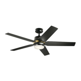
- Page 1 52" Maeve LED Product images may vary slightly from actual product. INSTRUCTION MANUAL...
- Page 2 2 | KICHLER.COM...
-
Page 3: Table Of Contents
TABLE OF CONTENTS SAFETY RULES ..............4 ATTACHING THE FAN BLADES .........12 TOOLS REQUIRED ............5 INSTALLING THE SWITCH HOUSING .....13 PACKAGE CONTENTS ............5 INSTALLING THE LIGHT KIT AND GLASS ....14 MOUNTING OPTIONS ............ 6 INSTALLING THE GLASS SHADE ......14 HANGING THE FAN ............7 OPERATING INSTRUCTIONS ........15 INSTALLATION OF SAFETY SUPPORT .... -
Page 4: Safety Rules
SAFETY RULES CAUTION – RISK OF SHOCK – To operate the reverse function on this fan, press the Disconnect Power at the main circuit breaker panel or “Reverse” button while fan is running. main fusebox before starting and during the installation. Avoid placing objects in the path of the blades. -
Page 5: Package Contents
TOOLS AND MATERIALS REQUIRED • Phillips Screwdriver • Blade Screwdriver • 11 mm Wrench • Step Ladder • Wire Cutters PACKAGE CONTENTS Unpack your fan and check the contents. You should have the following items: A. Mounting Bracket K. Remote Control Kit: Remote Control (1) B. -
Page 6: Mounting Options
MOUNTING OPTIONS If there isn’t an existing UL (cUL for Canadian Installation) listed mounting box, then read the following instructions. Disconnect the power by removing fuses or turning off circuit breakers. Outlet box Secure the outlet box directly to the building structure. Use appropriate fasteners and building materials. -
Page 7: Hanging The Fan
HANGING THE FAN Outlet Box REMEMBER to turn off the power before you begin installation. This is necessary for Ceiling Mounting Bracket your safety and also the proper programming of the control system. Flat Washer Screw To properly install your ceiling fan, follow the steps below. Fig. - Page 8 Hairpin Clevis Pin HANGING THE FAN (continued) Set Screw Hairpin Step 4. Carefully feed fan wires and safety cable up through the downrod. Clevis Pin Set Screw Thread the downrod onto the motor coupling until the clevis pin holes are aligned.
-
Page 9: Installation Of Safety Support
INSTALLATION OF SAFETY SUPPORT (required for Canadian installation ONLY) Flat Washer A safety support cable is provided to help prevent the ceiling fan from faIling, please Wood Screw Support Brace install it as follows. Spring Washer Ceiling Outlet Box Step 1. Drive a wood screw and washers into the side of the brace that holds the outlet box. -
Page 10: Electrical Connections
Mounting Bracket MAKE THE ELECTRICAL CONNECTIONS Receiver WARNING: To avoid possible electrical shock, be sure you have turned off the power at the main circuit panel before wiring. Follow the steps below to connect the fan to your household wiring. Use the wire connectors supplied with your fan. -
Page 11: Finishing The Motor Installation
MAKE THE ELECTRICAL CONNECTIONS Step 4. If your outlet box has a ground wire (green or bare copper) connect it to the fan ground wires: otherwise connect the fan ground wire to the mounting Mounting Bracket bracket. Secure the wire connection with a plastic nut provided. After connecting the wires, spread them apart so that the green and white wires are on one side of the outlet box and black and blue wires are on the other side. -
Page 12: Attaching The Fan Blades
FINISHING THE MOTOR INSTALLATION Shoulder Screw Step 3. Securely attach and tighten the canopy hole cover over the shoulder screws in the mounting bracket utilizing the keyslot twist-lock feature. (Fig. 17) Canopy Hole Cover ATTACHING THE FAN BLADES NOTE: Before continuing, make sure the power is disconnected by turning off the circuit breaker or removing the fuse at the circuit box. -
Page 13: Installing The Switch Housing
INSTALLING THE SWITCH HOUSING Step 1. Remove the screw marked with a dot label which is preinstalled on mounting plate and keep for later use. Loosen the other two (do not remove). Place the two slot holes on the switch housing over the 2 screws previously loosened from the mounting plate. -
Page 14: Installing The Light Kit And Glass
INSTALLING THE LIGHT KIT AND GLASS NOTE: Before continuing installation, confirm that the power is still turned off at the main circuit breaker or by removing the circuit fuse. Turning the power off using a wall switch is not sufficient to prevent electrical stock. Step 1. -
Page 15: Operating Instructions
OPERATING INSTRUCTIONS Step 1. Select a location to install your handset control holder, install the holder as shown. (Fig. 22) Batteries Step 2. Using a screwdriver, remove the battery cover from the handset and save the screw for later use. (Fig. 23) Fig. - Page 16 OPERATING INSTRUCTIONS NOTE: Each handset control carries a unique ID code to facilitate communication between paired devices. The ID code is set by factory and is not user changeable. However, you will be required to perform an “ID code learning” process manually under these circumstances: •...
-
Page 17: Troubleshooting
TROUBLESHOOTING Problem Solution Fan will not start. 1. Check circuit fuses or breakers. 2. Check all electrical connections to ensure proper contact. CAUTION: Make sure the main power is OFF when checking any electrical connection. 3. Make sure the transmitter batteries are installed properly. 4. - Page 18 TROUBLESHOOTING Problem Solution Fan wobble. 1. Check that all blade and blade arm screws are secure. 2. Most fan wobbling problems are caused when blade levels are unequal. Check this level by selecting a point on the ceiling above the tip of one of the blades. Measure this distance. Rotate the fan until the next blade is positioned for measurement.
-
Page 19: Fcc Information
FCC INFORMATION This device complies with part 15 of the FCC Rules. Operation is subject to the following two conditions: 1) This device may not cause harmful interference, and 2) This device must accept any interference received, including interference that may cause undesired operation. Note: This equipment has been tested and found to comply with the limits for a Class B digital device, pursuant to part 15 of the FCC Rules. - Page 20 KICHLER LIGHTING 7711 EAST PLEASANT VALLEY ROAD CLEVELAND, OHIO 44131 CUSTOMER SERVICE 866.558.5706 8:00 AM TO 5:00 PM EST, MONDAY - FRIDAY © Kichler Lighting LLC. All Rights Reserved.
- Page 21 52" Maeve LED Les images du produit peuvent varier légèrement par rapport au produit réel. MANUEL D'INSTRUCTIONS...
- Page 22 2 | KICHLER.COM...
- Page 23 TABLE DES MATIÈRES RÈGLES DE SÉCURITÉ ..........4 FIXATION DES LAMES DU VENTILATEUR ..12 OUTILS NÉCESSAIRES ..........5 INSTALLATION DU BOÎTIER DE COMMUTATEUR ............13 CONTENU DU COLIS ..........5 INSTALLATION DU KIT D’ÉCLAIRAGE OPTIONS DE MONTAGE ..........6 ET DU VERRE ............14 SUSPENDRE LE VENTILATEUR ......
-
Page 24: Règles De Sécurité
RÈGLES DE SÉCURITÉ Pour activer la fonction d'inversion sur ce ventilateur, appuyez sur le bouton « Inversion » pendant que le ventilateur fonctionne. ATTENTION : RISQUE DE CHOC : Évitez de placer des objets sur la trajectoire des pales. Débranchez l'alimentation au panneau du disjoncteur Pour éviter des blessures corporelles ou des dommages au principal ou à... -
Page 25: Contenu Du Colis
OUTILS ET MATÉRIAUX NÉCESSAIRES • Tournevis cruciforme • Tournevis à lame • Clé de 11 mm • Escabeau • Pinces coupantes CONTENU DU COLIS Déballez votre ventilateur et vérifiez le contenu. Vous devriez avoir les éléments suivants : A. Support de montage K. -
Page 26: Options De Montage
OPTIONS DE MONTAGE S'il n'y a pas de boîtier de montage homologué UL (cUL pour installation canadienne), lisez les instructions suivantes. Débranchez l'alimentation en retirant les fusibles ou en désactivant les disjoncteurs. Boîtier de sortie Fixez le boîtier de sortie directement à la structure du bâtiment. Utilisez des fixations et des matériaux de construction Fig. -
Page 27: Suspendre Le Ventilateur
SUSPENDRE LE VENTILATEUR Boîtier de sortie RAPPELEZ-VOUS de couper l'alimentation avant de commencer l'installation. Ceci est Support de montage au plafond nécessaire pour votre sécurité et également pour la bonne programmation du système Rondelle plate de commande. Pour installer correctement votre ventilateur de plafond, suivez les étapes ci-dessous. Fig. - Page 28 Épingle Axe de chape SUSPENDRE LE VENTILATEUR (suite) Vis de réglage Épingle Étape 4. Faites passer avec précaution les fils du ventilateur et le câble Vis de réglage Axe de chape de sécurité à travers la tige descendante. Vissez la tige descendante sur l'accouplement du moteur jusqu'à...
-
Page 29: Installation Du Support De Sécurité
INSTALLATION DU SUPPORT DE SÉCURITÉ (requis pour l'installation canadienne UNIQUEMENT) Rondelle plate Vis à bois Renfort de soutien Rondelle à ressort Un câble de support de sécurité est fourni pour aider à empêcher le ventilateur de Plafond Boîtier de sortie plafond de tomber, veuillez l'installer comme suit. -
Page 30: Raccordements Électriques
Support de montage EFFECTUER LES RACCORDEMENTS Récepteur ÉLECTRIQUES AVERTISSEMENT : Pour éviter tout risque d'électrocution, assurez-vous d'avoir coupé l'alimentation au panneau de circuit principal avant de procéder au câblage. Suivez les étapes ci-dessous pour raccorder le ventilateur à votre câblage domestique. Utilisez les connecteurs de fils fournis avec votre ventilateur. -
Page 31: Finition De L'installation Du Moteur
EFFECTUER LES RACCORDEMENTS ÉLECTRIQUES Support de montage Étape 4. Si votre boîtier de sortie a un fil de terre (cuivre vert ou nu), raccordez- le aux fils de terre du ventilateur : sinon raccordez le fil de terre du ventilateur au support de montage. -
Page 32: Fixation Des Lames Du Ventilateur
FINITION DE L'INSTALLATION DU MOTEUR Vis à épaulement Étape 3. Fixez et serrez solidement le couvercle du trou de l'auvent sur les vis à épaulement du support de montage en utilisant la fonction de verrouillage par Couvercle du trou de l'auvent rotation de la rainure de clé. -
Page 33: Installation Du Boîtier De Commutateur
INSTALLATION DU BOÎTIER DE COMMUTATEUR Étape 1. Retirez la vis marquée d'une étiquette à points qui est préinstallée sur la plaque de montage et conservez-la pour une utilisation ultérieure. Desserrez les deux autres (ne pas les enlever).Placez les deux trous de fente sur le boîtier du commutateur sur les 2 vis précédemment desserrées depuis la plaque de montage. -
Page 34: Installation Du Kit D'éclairage Et Du Verre
INSTALLATION DU KIT D'ÉCLAIRAGE ET DU VERRE REMARQUE : Avant de poursuivre l'installation, vérifiez que l'alimentation est toujours coupée au niveau du disjoncteur principal ou en retirant le fusible du circuit. La mise hors tension à l'aide d'un interrupteur mural ne suffit pas pour éviter les électrocutions. -
Page 35: Instructions D'utilisation
INSTRUCTIONS D'UTILISATION Étape 1. Sélectionnez un emplacement pour installer le support de votre télécommande, installez le support comme indiqué. (Fig. 22) Piles Étape 2. À l’aide d’un tournevis, retirez le couvercle de la batterie du combiné et conservez la vis pour une utilisation ultérieure. (Fig. 23) Fig. - Page 36 INSTRUCTIONS D'UTILISATION REMARQUE : Chaque télécommande porte un code d'identification unique pour faciliter la communication entre les appareils couplés. Le code d'identification est défini en usine et n'est pas modifiable par l'utilisateur. Cependant, vous devrez effectuer manuellement un processus « d'apprentissage du code d'identification » dans ces circonstances : CR2032 3V CR2032 3V •...
-
Page 37: Dépannage
DÉPANNAGE Problème Solution Le ventilateur ne 1. Vérifiez les fusibles ou les disjoncteurs. démarre pas. 2. Vérifiez tous les raccordements électriques pour assurer un bon contact. ATTENTION : Assurez-vous que l'alimentation principale est coupée lors de la vérification de tout raccordement électrique. - Page 38 DÉPANNAGE Problème Solution Le ventilateur vacille. 1. Vérifiez que toutes les vis de la pale et du bras de pale sont bien fixées. 2. La plupart des problèmes d'oscillation du ventilateur sont causés lorsque les niveaux des pales sont inégaux. Vérifiez ce niveau en sélectionnant un point sur le plafond au-dessus de la pointe de l'une des pales.
-
Page 39: Informations Fcc
INFORMATIONS FCC Cet appareil est conforme aux exigences de la section 15 du règlement de la FCC. Fonctionnement assujetti aux deux (2) conditions d’utilisation suivantes : 1) Cet appareil ne doit pas provoquer d'interférences nuisibles, et 2) Cet appareil doit accepter tous les brouillages reçus, y compris ceux pouvant causer un fonctionnement indésirable. Remarque : Cet équipement a été... - Page 40 KICHLER LIGHTING 7711 EAST PLEASANT VALLEY ROAD CLEVELAND, OHIO 44131 SERVICE À LA CLIENTÈLE 866.558.5706 8 h à 17 h EST, DU LUNDI AU VENDREDI © Kichler Lighting LLC. Tous droits réservés.
- Page 41 52" Maeve LED Las imágenes del producto pueden diferir ligeramente del producto real. MANUAL DE INSTRUCCIONES...
- Page 42 2 | KICHLER.COM...
- Page 43 ÍNDICE NORMAS DE SEGURIDAD........4 COLOCACIÓN DE LAS ASPAS DEL VENTILADOR ...........12 HERRAMIENTAS NECESARIAS ......5 INSTALACIÓN DE LA CARCASA CONTENIDO DEL PAQUETE........5 DEL INTERRUPTOR ..........13 OPCIONES DE MONTAJE .........6 INSTALACIÓN DEL KIT DE ILUMINACIÓN Y EL VIDRIO ..............14 COLGAR EL VENTILADOR ........7 INSTRUCCIONES DE FUNCIONAMIENTO ..
-
Page 44: Normas De Seguridad
NORMAS DE SEGURIDAD las pilas de manera adecuada y manténgalas alejadas de los niños. Incluso las pilas usadas pueden causar lesiones. Para operar la función de retroceso en este ventilador, PRECAUCIÓN - RIESGO DE CHOQUE - presione el botón “Retroceso” mientras el ventilador está Desconecte la energía en el panel del disyuntor principal funcionando. -
Page 45: Herramientas Necesarias
HERRAMIENTAS Y MATERIALES REQUERIDOS • Destornillador Phillips • Destornillador plano • Llave de 11 mm • Escalera de mano • Cortadores de alambre CONTENIDO DEL PAQUETE Desempaque su ventilador y verifique el contenido. Debería tener los siguientes elementos: A. Soporte de montaje K. -
Page 46: Opciones De Montaje
OPCIONES DE MONTAJE Si no existe una caja de montaje con certificación UL (cUL para la instalación canadiense), lea las siguientes instrucciones. Desconecte la energía quitando los fusibles o apagando los disyuntores. Caja de salida Fije la caja de distribución directamente a la estructura del edificio. -
Page 47: Colgar El Ventilador
COLGAR EL VENTILADOR Caja de salida RECUERDE desconectar la alimentación antes de comenzar la instalación. Esto es necesario Soporte de montaje del techo para su seguridad y también para la programación adecuada del sistema de control. Arandela plana Tornillo Para instalar correctamente su ventilador de techo, siga los pasos a continuación. Figura 5 Paso 1. - Page 48 Horquilla Pasador de horquilla COLGAR EL VENTILADOR (continuación) Tornillo de fijación Horquilla Paso 4. Pase con cuidado los cables del ventilador y el cable de seguridad Pasador de horquilla Tornillo de fijación hacia arriba a través de la varilla de extensión. Enrosque la varilla de extensión en el acoplamiento del motor hasta que los orificios del pasador de horquilla estén alineados.
-
Page 49: Instalación De Soporte De Seguridad
INSTALACIÓN DEL SOPORTE DE SEGURIDAD (requerido para la instalación canadiense SOLAMENTE) Arandela plana Tornillo para madera Soporte de apoyo Arandela de resorte Se proporciona un cable de soporte de seguridad para ayudar a evitar que el ventilador Techo Caja de salida de techo se caiga;... -
Page 50: Conexiones Eléctricas
Soporte de montaje REALIZAR LAS CONEXIONES ELÉCTRICAS Receptor ADVERTENCIA: Para evitar posibles descargas eléctricas, asegúrese de haber desconectado la energía en el panel del circuito principal antes de realizar el cableado. Siga los pasos a continuación para conectar el ventilador al cableado de su hogar. Utilice los conectores de cable suministrados con su ventilador. -
Page 51: Finalización De La Instalación Del Motor
REALIZAR LAS CONEXIONES ELÉCTRICAS Paso 4. Si su caja de salida tiene un cable de tierra (de cobre verde o desnudo) conéctelo a los cables de tierra del ventilador; de lo contrario, conecte el cable Soporte de montaje de tierra del ventilador al soporte de montaje. Fije la conexión del cable con una tuerca de plástico proporcionada. -
Page 52: Colocación De Las Aspas Del Ventilador
FINALIZACIÓN DE LA INSTALACIÓN DEL MOTOR Tornillo de resalto Cubierta del Paso 3. Fije y apriete firmemente la cubierta del orificio del dosel sobre los orificio del dosel tornillos de resalto en el soporte de montaje utilizando la función de bloqueo por giro de la ranura de llave. -
Page 53: Instalación De La Carcasa Del Interruptor
INSTALACIÓN DE LA CARCASA DEL INTERRUPTOR Paso 1. Retire el tornillo marcado con una etiqueta de punto que está preinstalado en la placa de montaje y guárdelo para su uso posterior. Afloje los otros dos (no los quite). Coloque los dos orificios de la ranura en la carcasa del interruptor sobre los 2 tornillos que aflojó... -
Page 54: Instalación Del Kit De Iluminacióny El Vidrio
INSTALACIÓN DEL KIT DE LUZ Y VIDRIO NOTA: Antes de continuar con la instalación, confirme que la energía aún está apagada en el disyuntor principal o retirando el fusible del circuito. Apagar la alimentación con un interruptor de pared no es suficiente para evitar descargas eléctricas. -
Page 55: Instrucciones De Funcionamiento
INSTRUCCIONES DE FUNCIONAMIENTO Paso 1. Seleccione una ubicación para instalar el soporte del control remoto, instale el soporte como se muestra. (Figura 22) Baterías Paso 2. Con un destornillador, quite la tapa de las pilas del dispositivo y guarde el tornillo para usarlo más tarde. (Figura 23) Figura 22 Figura 24 Paso 3. - Page 56 INSTRUCCIONES DE FUNCIONAMIENTO NOTA: Cada control remoto lleva un código de identificación único para facilitar la comunicación entre dispositivos emparejados. El código de identificación viene configurado de fábrica y el usuario no puede cambiarlo. Sin embargo, se le pedirá que realice un proceso de “aprendizaje del código de identificación”...
-
Page 57: Resolución De Problemas
RESOLUCIÓN DE PROBLEMAS Problema Solución El ventilador 1. Verifique los fusibles o disyuntores del circuito. no arranca. 2. Verifique todas las conexiones eléctricas para asegurar un contacto adecuado. PRECAUCIÓN: Asegúrese de que la alimentación principal esté APAGADA cuando verifique cualquier conexión eléctrica. - Page 58 RESOLUCIÓN DE PROBLEMAS Problema Solución Oscilación del 1. Verifique que todos los tornillos de aspa y del brazo de aspa estén firmes. ventilador. 2. La mayoría de los problemas de oscilación del ventilador se deben a que los niveles de las aspas no son iguales.
-
Page 59: Información De La Fcc
INFORMACIÓN DE LA FCC Este dispositivo cumple con la parte 15 de las normas de la Comisión Federal de Comunicaciones (Federal Communications Commission, FCC). El funcionamiento está sujeto a las siguientes dos condiciones: 1) Este dispositivo no puede causar interferencias perjudiciales, y 2) Este dispositivo debe aceptar cualquier interferencia recibida, incluidas interferencias que puedan causar un funcionamiento no deseado. - Page 60 KICHLER LIGHTING 7711 EAST PLEASANT VALLEY ROAD CLEVELAND, OHIO 44131 SERVICIO AL CLIENTE 866.558.5706 8:00 AM A 5:00 PM EST, DE LUNES A VIERNES © Kichler Lighting LLC. Todos los derechos reservados.
Need help?
Do you have a question about the Maeve LED 52 and is the answer not in the manual?
Questions and answers