Advertisement
Available languages
Available languages
Quick Links
INSTRUCTION
EN
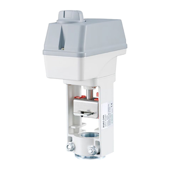
RVA10-24A
i
Read this instruction before installation
and wiring of the product
Valve actuator for 0(2)...10 V control
RVA10-24A is a valve actuator designed for control of NTVS, FRS and
2SAS valves, as well as 2SBS valves with DN20...DN80. The actuator
has automatic self stroke adjustment and can be operated manually.
Technical data
Supply voltage
24 V AC ±15%, 50/60 Hz
Control signal
0(2)...10 V DC
Power consumption
Max. 6 W
Stroke
10...30 mm (20 mm fixed stroke)
Stroke time
3 s/mm
Force
1000 N
Ambient temperature
0...50°C
Storage temperature
-40...80°C
Ambient humidity
10...90% RH
Dimensions
150 x 250 x 85 mm
Protection class
IP54
Installation
If the valve stem adaptor and valve throat adaptor are not already
mounted on the valve, mount them. Pull the valve stem out as far as
possible.
Remove the locking bolt (U-bolt) from the actuator yoke. Insert the valve
stem into the yoke and make sure that the stem adaptor engages the hole
in the angled iron of the actuator drive spindle.
The groove in the valve throat adaptor must be made to line up with the
U-bolt mounting holes on the actuator. If the spindle needs moving in or
out for this to happen, depress the central part of the manual button and
turn it clockwise for the actuator spindle to extend, and anti-clockwise for it
to retract (see Manual override). When the valve is in the correct position,
insert the U-bolt. Tighten the bolt nuts until the valve is firmly gripped.
Disassembly in reverse order.
Mounting positions
85º
Wiring
U
M
9
8
7
5
4
U 0...10 V DC
Measuring voltage
for position indication
Y 0(2)...10 V DC
Control signal from
controller
Automatic stroke and endpoint calibration
On each power-up and after manual manoeuvring, automatic stroke and
endpoint calibration will take place. If the unit has been configured for
fixed stroke (DIP-switch 2 in position Off) the actuator will first go to the
fully closed end position. The position will be stored in memory and the
stroke will be calculated from this point.
If the unit has been configured for free stroke (DIP-switch 2 in position
RVA10-24A
On) the actuator will first go to both endpoints of the stroke. The
points will be stored in memory and the control will be calibrated so
that the full stroke will be covered by the set input signal.
Override
Activation of the override input will force the actuator spindle to go to
its lowest position or its highest position, depending on the setting of
DIP-switch SW1. SW1 also affects the direction of movement.
Manual override
85º
To manually set the valve position, first depress the central part of
the button until it clicks and remains depressed (1 in the figure). This
B
Y
disengages the gears and also cuts the power to the motor. Then the
6
3
2
1
valve position can be changed manually by turning the button (2 in
the figure). Clockwise rotation will extend the drive rod and anti-clock-
wise will retract it.
To reconnect power, set the button so the flats are in line with the
cutout in the edge of the cover, Auto position. Then press on the outer
parts of the button (3 in the figure). The central depressed part will
pop out re-engaging the gears and reconnecting the power.
Note: After any manual operation the actuator will always run through
a full stroke and endpoint calibration.
DIP-switches
There are seven DIP-switches for setting different functions. Follow
the table below for setting the DIP-switches.
24 V AC
Changes of the setting for SW2 will take effect immediately. Changes
of the other positions will be ignored during operation. New settings
will be valid only after the next power-on.
SW1
1 (On)
0 (Off)
Spindle up on closed
Spindle down on closed
contact
contact (FS=factory setting)
1
Advertisement

Related Manuals for Regin RVA10-24A


Summary of Contents for Regin RVA10-24A
- Page 1 Valve actuator for 0(2)...10 V control the figure). Clockwise rotation will extend the drive rod and anti-clock- wise will retract it. RVA10-24A is a valve actuator designed for control of NTVS, FRS and To reconnect power, set the button so the flats are in line with the 2SAS valves, as well as 2SBS valves with DN20...DN80. The actuator cutout in the edge of the cover, Auto position. Then press on the outer has automatic self stroke adjustment and can be operated manually.
- Page 2 5(6)...10 V = 0...100% 0(2)...5(6) V = 0...100% linkage. The markers can easily be moved in order to show when the RVA10-24A är ett ventilställdon för styrning av NTVS-, FRS- och (FS) actuator is closed/open for heating/cooling. 2SAS-ventiler, samt 2SBS-ventiler med DN20...DN80. Ställdonet har For heating valves, the red marker should be in the completely open valve automatisk lyfthöjdsjustering och kan köras manuellt.
- Page 3 Produkten uppfyller kraven för europeiska LVD-standard och systemnoll (plint 2) och SW4 ställas till 2...10 V DC. Styrsignalen EN60730-1:2000 och EN60730-2-8:2002. kommer då att omvandlas till 2...10 V DC. Teknisk support Teknisk hjälp och råd på telefon: 031 720 02 30 RVA10-24A...
-
Page 4: Installation
Produkt installieren und anschließen Ventilstellantrieb zur 0(2)...10 V Regelung RVA10-24A ist ein Ventilstellantrieb, der mit den NTVS-, FRS- und 2SAS- Ventilen sowie den 2SBS-Ventilen in Größe DN20...DN80 verwendet wird. Anschluss Der Stellantrieb hat eine automatische Hub-Adaption und kann manuell betrieben werden. - Page 5 Einstellung ist beim nächsten Start Freier Hubweg (Autoanpas- Fester Hubweg (20 mm) gültig. sung, 10...30 mm) (WE) Rotes und stetiges grünes Endposition erreicht Linear Gleiches Verhältnis (WE) Licht Y = 2...10 V DC Y = 0...10 V DC (WE) Gegenlauf Direktlauf (WE) RVA10-24A...
- Page 6 Commande manuelle Moteur de vanne pour contrôle 0(2)...10 V RVA10-24A est un actionneur qui permet de commander les vannes NTVS, FRS et 2SAS ainsi que les vannes DN20 à DN80 de la gamme 2SBS. Ce moteur a un réglage automatique de la course et peut être Raccordement manœuvré...
- Page 7 à la fonction split. Le réglage de SW6 permet d’activer/désacti- Contact ver cette fonction. SW7 permet de déterminer la plage de fonctionne- ment de l’actionneur. Regin Control SARL, 32 rue Delizy, 93500 Pantin Tél : 01 41 71 00, Fax : 01 41 76 76 www.regin.fr, info@regin.fr Voyants d’indication L’actionneur est équipé de deux voyants LED dont la signification est...
Need help?
Do you have a question about the RVA10-24A and is the answer not in the manual?
Questions and answers