Advertisement
Available languages
Available languages
Quick Links
INSTRUCTION
EN
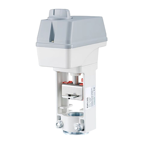
RVAN5-24A
i
Read this instruction before installation
and wiring of the product
Valve actuator for 0(2)...10 V control
RVAN5-24A is a valve actuator designed for control of Regin valves.
The actuator has automatic self stroke adjustment and can be oper-
ated manually.
Technical data
Supply voltage
24 V AC ±15 %, 50/60 Hz
or 24 V DC ±15 %
Control signal
0(2)...10 V DC
Power consumption
Max. 4.5 W
Stroke
10...30 mm
Stroke time
1.5 s/mm
Force
500 N
Ambient temperature
0...50°C
Storage temperature
-40...80°C
Ambient humidity
10...90 % RH
Dimensions (WxHxD)
150 x 253 x 85 mm
Protection class
IP54
Installation
If the valve stem adaptor and valve throat adaptor are not already mount-
ed on the valve, mount them. Pull the valve stem out as far as possible.
Remove the locking bolt (U-bolt) from the actuator yoke. Insert the valve
stem into the yoke and make sure that the stem adaptor engages the hole
in the angled iron of the actuator drive spindle.
The groove in the valve throat adaptor must be made to line up with the
U-bolt mounting holes on the actuator. If the spindle needs moving in or
out for this to happen, depress the central part of the manual button and
turn it clockwise for the actuator spindle to extend, and anti-clockwise for
it to retract (see Manual override). When the valve is in the correct posi-
tion, insert the U-bolt. Tighten the bolt nuts until the valve is firmly gripped.
Disassembly in reverse order.
Mounting positions
90º
Wiring
U
5
Measuring voltage
for position indication
U 0...10 V DC
Signal neutral
Y 0(2)...10 V DC
Control signal from
controller
Stroke and end position calibration
Stroke and end position calibration is not necessary due to a construction
utilizing end position stops. When the valve reaches the end position, a
force is generated. Once the force of the actuator reaches a predefined
level, the limit switch automatically halts the drive motor.
RVAN5-24A
Override
Activation of the override input will force the valve to the maximum
open position.
Manual override
90º
To manually set the valve position, first depress the central part of the
knob, until it clicks and remains depressed (1 in the figure). Then the
valve position can be changed manually by turning the knob (2 in the
figure). When the knob is turned clockwise, the drive rod is pushed
outwards and when the knob is turned anti-clockwise, the drive rod is
pulled inwards.
To return to normal operation, set the knob so that it is in line with the
text "Auto" on the cover. Then depress the outer parts of the knob (3
in the figure). The central depressed part will pop out, and the actua-
tor will return to normal operation.
G0
G
B
M
Y
Note: After any manual operation the actuator will always run through
6
4
3
2
1
a zero point calibration.
DIP switches
There are five DIP switches for setting different functions. Follow the
table below for setting the DIP switches.
Adjusted settings will be valid only after the next power-on.
SW1
SW2
24 V AC/DC
SW3
SW4
SW5
1 (On)
0 (Off)
Spindle down when the
Spindle up when the valve is
valve is closed
closed (FS=factory setting)
Y = 2...10 V DC
Y = 0...10 V DC (FS)
Reverse operation
Direct operation (FS)
Y signal split in accordance
No split function (FS)
with the setting of SW5
5(6)...10 V = 0...100 %
0(2)...5(6) V = 0...100 % (FS)
1
Advertisement

Subscribe to Our Youtube Channel
Related Manuals for Regin RVAN5-24A


Summary of Contents for Regin RVAN5-24A
- Page 1 Valve actuator for 0(2)...10 V control Note: After any manual operation the actuator will always run through a zero point calibration. RVAN5-24A is a valve actuator designed for control of Regin valves. The actuator has automatic self stroke adjustment and can be oper- DIP switches ated manually.
-
Page 2: Installation
In this case, a 500 Ohm resistor should be installed between the control signal input (terminal 3) and system neutral (terminal 2) RVAN5-24A är ett ventilställdon för styrning av Regins ventilsorti- and SW2 should be set to position On (2...10 V DC). - Page 3 Rött ljus som blinkar långsamt Driftläget överstyrs När överstyrningsingången aktiveras tvingas ventilen till maximalt 5(6)...10 V = 0...100 % 0(2)...5(6) V = 0...100 % (FI) Fast rött ljus Felaktigt handhavande, an- öppet läge. tingen var installationen felaktig eller så gick ventilens slaglängd förlorad RVAN5-24A...
- Page 4 Vid kylventil ska den blå markeringen vara i läge för helt öppen ventil och den röda markeringen i läge för helt stängd ventil. Ventilstellantrieb für 0(2)...10 V-Ansteuerung RVAN5-24A ist ein Stellantrieb für die Ansteuerung von Regin Ventilen. EMC emissions- och immunitetsstandard Anschluss...
-
Page 5: Dip-Schalter
Keine Splittung (WE) chend Einstellung an SW5 Stetiges rotes und grünes Endlage erreicht Licht 5(6)...10 V = 0...100 % 0(2)...5(6) V = 0...100 % (WE) Rotes, langsam blinkendes Betriebsmodus Übersteuerung Licht Stetiges rotes Licht Fehlfunktion; entweder inkorrekte Installation oder fehlender Hubweg RVAN5-24A... - Page 6 90º 90º l’installation et au raccordement de l’appareil. Moteur de vanne pour contrôle 0(2)...10 V L’actionneur RVAN5-24A est prévu pour le pilotage de vannes Regin. L’ajustement de la course est automatique. Le moteur dispose d’une Raccordement commande manuelle. Pour régler manuellement la position de la vanne, appuyez sur la Caractéristiques techniques...
- Page 7 Off : Fonction split inactive. Contact SW5 Plage de fonctionnement avec la fonction split Regin FRANCE, 32 rue Delizy, 93500 Pantin On : 5…10 V= 0…100 % (6…10 V quand SW2=On) Tél : +33(0)1 71 00 34, Fax : +33(0)1 71 46 46 Off : 0…5 V= 0…100 % (2…6 V quand SW2=On)
Need help?
Do you have a question about the RVAN5-24A and is the answer not in the manual?
Questions and answers