
Subscribe to Our Youtube Channel
Related Manuals for Baicells Nova430


Summary of Contents for Baicells Nova430
- Page 1 Nova430 Outdoor 4x250mW eNodeB Quick Guide P/N: 1701000177 Document version: 01 All rights reserved © Baicells Technologies Co., Ltd.
-
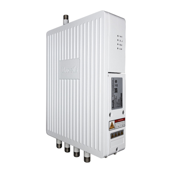
Page 2: Product Overview
5, 10, 15, or 20 MHz bandwidth. Using a Nova430 in DC mode simplifies and streamlines the deployment of split sectors. In addition to having the option to operate Nova430 in either CA or DC mode, HaloB (an embedded MME option) comes as a default feature in the base software. Baicells's patented HaloB solution migrates the necessary core network functions to the eNB. - Page 3 External antenna interface 2, N type connector ANT2 External antenna interface 3, N type connector ANT3 External antenna interface 4, N type connector The Nova430 interface indicators are described in Table 1-2. Table 1-2 Nova430 Interface Indicators Identity Color Status...
-
Page 4: Technical Specification
Identity Color Status Description Fast flash: 0.1s on,0.1s off CELL1 is in deactivated. Slow flash: 1s on,1s off CELL1 is in activated. CELL2 is in inactivated. CELL2 Green Fast flash: 0.1s on,0.1s off CELL2 is in deactivated. Slow flash: 1s on,1s off CELL2 is in activated. -
Page 5: Global Part Numbers
1.4.2 Global Part Numbers Model No. Description Band42/43/48, 10MHz, 20MHz per carrier, DL 2 x 2 on pBS3101SE each carrier, 2 carriers 1.4.3 Software Specification Item Description LTE Standard 3GPP Release 15 2x20 MHz: SA1: DL 2x80Mbps, UL 2x28Mbps SA2: DL 2x110Mbps, UL 2x14Mbps DC mode ... -
Page 6: Environment Specification
Item Description Support configuration management Support local or remote software upgrading and loading Support log Support connectivity diagnosis Support automatic start and configuration Support alarm reporting Support user information tracing Support signaling trace 1.4.4 Environment Specification Item Description Operating Temperature -40°... -
Page 7: Isedc Compliance
particular installation. If this equipment does cause harmful interference to radio or television reception, which can be determined by turning the equipment off and on, the user is encouraged to try to correct the interference by one or more of the following measures: ... -
Page 8: Installation Material
Les antennes utilisé es pour cet é metteur doivent être installées de faç on à offrir une distance de séparation d'au moins 50cm entre toutes les personnes et ne doivent pas être colocalisées ou fonctionner conjointement avec d'autres antennes ou transmetteurs. pour satisfaire la conformité... - Page 9 To protect the connection points from weather and climate, clean each connection point before installing cold shrink tubes, per the following figure. Insert the cable into the cold shrink tube. Tighten the connector. Push the cold shrink tube to the top joint, and pull out the strip. Ensure the cold shrink tube is tightly fitted with the connection.
-
Page 10: Install On Pole
No major blocking from buildings in the vicinity. Make sure the space atop is at least 45 degrees unblocked by any buildings. Avoid installing the GPS antenna in the vicinity of any other transmitting and receiving devices, to avoid interference. ... - Page 11 Figure 2-2 Pre-assembled Device Following will introduce how to fix the pre-assembled eNB on a pole.
-
Page 12: Install On Wall
Install on Wall NOTE: The wall must bear at least 4 times the weight of the eNB. Take apart assembly bracket first, only remains the wall bracket, as shown in Figure 2-3. Figure 2-3 Wall Bracket Following steps introduce how to fix the pre-assembled eNB on a wall. -
Page 13: Connect Cables
Connect Cables NOTE: The GPS antenna connector and the RF antenna connector must have weatherproof protection, refer to “2.3 Weatherproofing”. Power On Power on the eNB, and wait a few minutes while the eNB boots up. Per the previous Table 1-1 and Table 1-2 in “1.3 Appearance”, check that the LED indicators are lighting as expected.
Need help?
Do you have a question about the Nova430 and is the answer not in the manual?
Questions and answers