
Related Manuals for Baicells Neutrino-224


Summary of Contents for Baicells Neutrino-224
- Page 1 Neutrino-224 Indoor 2x125mW FDD/TDD eNodeB Installation Guide December 2018 Version 1.7...
- Page 2 About This Document This document is intended for anyone who will be installing the Baicells Neutrino-224 Indoor 2x125mW eNodeB (eNB). The 3GPP standards-based Neutrino eNB provides broadband wireless access to Long-Term Evolution (LTE) Frequency Division Duplexing (FDD) and Time Division Duplexing (TDD) backhaul networks. The information includes planning considerations, installation procedures, and configuration guidance.
- Page 3 Website www.Baicells.com https://na.Baicells.com Related Documents Other Baicells technical documents may be found at Baicells Support > Downloads. User Equipment: Atom 5dBi Indoor CPE User Manual Atom 11dBi Outdoor CPE User Manual Atom 19.5dBi Outdoor CPE User Manual Atom ID0406-6.5 User Manual...
- Page 4 For the safety of installation personnel and for the protection of the equipment from damage, please read all safety warnings. If you have any questions concerning the warnings, before installing or powering on the base station contact the Baicells support team. Warning IMPORTANT SAFETY INSTRUCTIONS This warning symbol means danger.
-
Page 5: Table Of Contents
Table of Contents 1 Overview ........................9 1.1 Introduction ......................... 9 1.2 Features ........................10 2 Planning ........................11 2.1 Network & Site Planning .................... 11 2.2 Mounting Options...................... 11 2.3 Client Computer Requirements ................. 11 2.4 Form Factor ........................ 12 3 Verify Basic Operation .................... - Page 6 Appendix C: Abbreviations & Acronyms ................84 List of Figures Figure 1-1: Neutrino-224 eNB ....................9 Figure 1-2: Baicells Broadband Wireless Access Solution with Neutrino-224 eNB ....10 Figure 2-1: Form Factor ......................12 Figure 2-2: LEDs & Interfaces ....................12 Figure 3-1: LEDs &...
- Page 7 Figure 5-17: License Management ..................39 Figure 5-18: NTP ........................40 Figure 5-19: Upgrade ....................... 41 Figure 5-20: Backup ......................... 42 Figure 5-21: CertStore ......................44 Figure 5-22: LTE Setting ......................45 Figure 5-23: LTE Freq/Cell ......................46 Figure 5-24: LTE Neigh Freq Settings (1 of 2) ................47 Figure 5-25: LTE Neigh Freq Settings (2 of 2) ................
- Page 8 List of Tables Table 2-1: Client Computer Requirements ................11 Table 2-2: LEDs & Interfaces ....................12 Table 2-3: LED Color States ...................... 13 Table 4-1: Computer Requirements ..................17 Table 5-1: Quick Setting ......................22 Table 5-2: WAN Interface ......................24 Table 5-3: Multi link mode configuration ................
-
Page 9: Overview
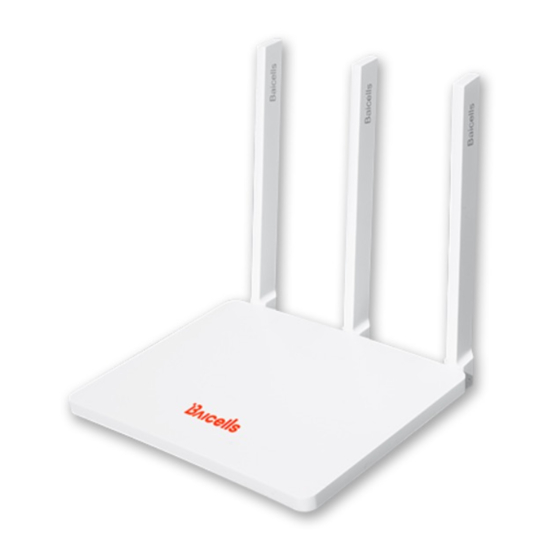
Overview 1.1 Introduction The Baicells Neutrino-224 product is an indoor 2x125mW small cell eNodeB (eNB) (Figure 1- 1). The eNB provides broadband wireless access to 3GPP standard Frequency Division Duplexing (FDD) and Time Division Duplexing (TDD) Long-Term Evolution (LTE) backhaul networks. -
Page 10: Features
The system architecture, including Neutrino-224 eNBs, is illustrated in Figure 1-2. Figure 1-2: Baicells Broadband Wireless Access Solution with Neutrino-224 eNB 1.2 Features The Neutrino-224 eNB is based on LTE Standard 3GPP Release 9. Following is a list of the key features of this product: • Standard LTE network modes:... -
Page 11: Planning
2.2 Mounting Options The Baicells Neutrino-224 eNB was designed for easy deployment. The unit can sit on a desktop or be installed on a ceiling or a wall. -
Page 12: Form Factor
2.4 Form Factor The Neutrino eNB has a sleek form factor (Figure 2-1): • Height with antennas – 7 inches / 175 mm • Height of base – 1 inch / 30 mm • Width – 5 inches / 130 mm The unit only weighs approximately one pound (500 g). -
Page 13: Table 2-3: Led Color States
*NOTE: Some users may want to add a GPS antenna to better ensure accurate physical location information used by the eNB during transmissions. Follow the GPS vendor’s installation requirements to install a GPS antenna with the Neutrino eNB. Table 2-3: LED Color States Color Status Description... -
Page 14: Verify Basic Operation
Verify Basic Operation Before installing the Neutrino eNodeB (eNB), especially if placing it on a ceiling or wall, you should check that: • You have all of the parts on the packing list; • You have the standard tools at hand to perform the installation; and •... -
Page 15: Mounting The Unit
Baicells Neutrino-224 eNB. 4.2 Ceiling Installation Review the following guidelines for installing the Neutrino-224 eNB unit on a ceiling. The installation steps follow. The thickness of the ceiling should be no less than ½ inch/18 mm, and should be able to ... -
Page 16: Figure 4-2: Mark Drilling Holes
Place the bracket on the center of the ceiling panel, and mark the drilling hole locations with a marker pen (Figure 4-2). Figure 4-2: Mark Drilling Holes Drill the 3 holes that you marked, deep enough to receive the expansion bolts. Use the expansion bolts to fix the installation bracket on the ceiling panel, and tighten the screws (Figure 4-3). -
Page 17: Wall Installation
Configuration. 4.6 Check eNB Status in Software The Baicells eNBs are designed to be plug-and-play and, therefore, arrive with many parameters pre-configured using default values. You will need to connect a computer to the LAN port using an Ethernet cable to ensure the eNB status is reported as active before you continue with the installation. -
Page 18: Prepare The Client Computer
4.6.2 Prepare the Client Computer 4.6.2.1 Connect Ethernet Cable Connect one end of an Ethernet cable to the LAN port on the eNB and the other end to your computer. Initially, you will use this local connection to access the eNB GUI application to verify the eNB’s status and to configure a few basic settings. -
Page 19: Enb Gui
The Cell Status field should indicate Activation (for Active). You are ready to go to the next step – section 5 Configuration. If the status is reported as inactive, check the SCTP/S1AP link or contact Baicells support. -
Page 20: Figure 4-7: Fdd Enb Gui Home Page
Figure 4-7: FDD eNB GUI Home Page Figure 4-8: TDD eNB GUI Home Page... -
Page 21: Configuration
The configuration procedures covered in this section are illustrated using the eNodeB (eNB) GUI. The information assumes you have read and completed the previous steps in section 4. For more information on Baicells network configuration and subscriber management, please refer to the Baicells Configuration &... -
Page 22: Figure 5-2: Tdd Quick Setting
Figure 5-2: TDD Quick Setting Table 5-1: Quick Setting Parameter Name Description carrierBwMhz The bandwidth used by the eNB, as pre-planned by the operator. Options are 5 MHz, 10 MHz, 15 MHz, or 20 MHz. EARFCN The absolute radio frequency channel number, assigned by the operator. -
Page 23: Network
Description 1 = DL:UL is 2:2 transmission ratio 2 = DL:UL is 3:1 transmission ratio (default) Refer to the BaiTip on this setting: https://community.na.baicells.com/t/baitip-of-the- day-december-14th-2016-subframes-and-special- subframes/163 specialSubframePatterns Either 5 or 7. This is a standard LTE setting that pertains to synchronization of downlink and uplink timing. -
Page 24: Figure 5-3: Wan
Figure 5-3: WAN Table 5-2: WAN Interface Parameter Name Description WAN Config Mac Config Enter the MAC address for the WAN interface. WAN Connect Mode Bridge Mode True or False WAN Connect Type Ethernet WAN1 Config IP Access Mode The interface protocol used by the WAN interface. Options are: ... -
Page 25: Lan
When more IP addresses are needed, set the Multi link mode configuration field to Enable (Figure 5-4). Table 5-3 provides a description of each field. Figure 5-4: Multi link mode configuration Table 5-3: Multi link mode configuration Multi link mode configuration MultiInterfacesConfig Enable or Disable. -
Page 26: Figure 5-5: Lan
Figure 5-5: LAN The LAN interface is enabled by default. If the IP address and Subnet mask need to be changed, input new values in the text fields. If you wish to enable Internet access for the LAN interface, at the LAN Internet Config field select Enabled. -
Page 27: Route
Parameter Name Description End IP Address Ending IP address of the DHCP server dhcpDNS1 DNS address 1 for the DHCP server dhcpDNS2 DNS address 2 for the DHCP server dhcpDNS3 DNS address 3 for the DHCP server Click on Save to save the configuration. 5.2.3 Route Follow the steps below to configure the static route for users with a static IP address. -
Page 28: Host
Classification Parameter Description onBoot Enable or disable an IPv6 default route. The default is disabled. IPV6 ROUTE Default Configuration netAddr If you enabled an IPv6 default route, set the IP address. onBoot On or Off V6 onBoot Enable or disable IPv6. The default is disabled. netAddr The target IP address. -
Page 29: Ipsec
Figure 5-8: Host Table 5-6: Host Parameter Name Description Host Name Host server name. Range: 0-63 digits. Time Zone Located time zone of the host server. Range: -12 to 12. dnsOnBoot Enable or disable Domain Name Server (DNS) function. DNS Address For DNS 1 –... -
Page 30: Figure 5-9: Ipsec
Figure 5-9: IPSec In the IPSec Setting area of the window, check that the IPSec function is set to Enabled (default). If the Enable field is set to Disabled, select Enable to enable the IPSec function. Click on Save to save the IPSec setting. If you wish to enable soft USIM, meaning users can use embedded rather than removable SIM cards, check that the default value of Enabled is selected in the softUsim field. -
Page 31: Figure 5-10: Ipsec Tunnel - Basic Setting
Figure 5-10: IPSec Tunnel – Basic Setting Table 5-7: IPSec Tunnel – Basic Setting Parameter Name Description Enabled Enable or disable the IPSec tunnel. The default value is Enabled. leftAuth Attention: DO NOT change this value! Local authentication type of the IPSec. Must be consistent with the security gateway side. - Page 32 Parameter Name Description consistent with the security gateway side. leftId Local ID of the client, 0-64 digit string. Must be consistent with the security gateway side. If absent from the security gateway, leave it empty here. rightId Peer ID of the server, 0-64 digit string. Must be consistent with the security gateway side.
-
Page 33: Figure 5-11: Ipsec Tunnel - Advance Setting
Figure 5-11: IPSec Tunnel – Advance Setting Table 5-8: IPSec Tunnel – Advance Setting Parameter Name Description IKE Encryption IKE encryption algorithm. Options: aes128 • • aes256 • 3des • IKE DH Group IKE DH group. Options: modp768 • • modp1024 •... - Page 34 Parameter Name Description IKE Authentication Authentication algorithm. Options: • sha1 sha1_160 • • sha256_96 • sha256 ESP Encryption ESP encryption algorithm. Options: aes128 • aes256 • • 3des • ESP DH Group ESP DH group. Options: modp768 • • modp1024 •...
-
Page 35: Backhaul
5.2.6 BACKHAUL Use the BACKHAUL menu (Figure 5-12) to configure the backhaul ping setup for the eNB. For example, you can set it up to ping the OMC, MME, or edge gateway. The fields are described in Table 5-9. Select Save to retain the settings. Ping results, ping summary, and ping status will display In the lower half of the window.. -
Page 36: Bts Setting
5.3 BTS Setting 5.3.1 Security Setting The Security Setting menu (Figure 5-13) pertains to the LTE encryption algorithms that will be used. For the Neutrino eNB we do not recommend changing any of the default values. The fields are described in Table 5-10. Caution: DO NOT modify the security parameters;... -
Page 37: Sync Setting
Figure 5-14: Management Server 5.3.3 Sync Setting The LTE technology standards specify timing and synchronization requirements between adjacent eNBs. Synchronizing transmissions helps to avoid eNBs interfering with one another, optimize bandwidth usage, and enhance network capacity. Go to BTS Setting > Sync Setting (FDD in Figure 5-15, TDD in Figure 5-16). Refer to Table 5-11 for a description of each field. -
Page 38: Figure 5-16: Tdd Sync Setting
Figure 5-16: TDD Sync Setting Table 5-11: Sync Setting Parameter Name Description TFCS Management Config: primSrc Primary Transport Format Combination (TFC) synchronization source. Options: • • • GNSS: only GPS is supported. • • EXT_CLK • EXT_PPS FREE_RUNNING • Sync Mode Synchronization mode. -
Page 39: License Management
PLMN IDs, separated by commas. NL Sync Cell Information (display): Provides the result of NL synchronization; contains cell information Geographic Location Information (display): Provides the result of GPS synchronization; contains the geographic location information Satellite Information (display): Provides the result of GPS synchronization; contains the satellite information 5.3.4 License Management Use the License Management menu (Figure 5-17) to upload certificate files, such as... -
Page 40: Upgrade
Figure 5-18: NTP Table 5-12: NTP Parameter Name Description onBoot Enable or disable the NTP function Port Port number of the master NTP server. Must be consistent with the other end. Range: 1 to 65535 Server1 Domain name or IP address of the master NTP server. Must be consistent with the other end. -
Page 41: Figure 5-19: Upgrade
Refer to Figure 5-19, and follow the steps below to upgrade the version of eNB firmware. From the Baicells website or OMC, download the file with the new version of firmware and save it to a local computer. Be sure the file you select is appropriate for the model of Neutrino eNB being upgraded, e.g., either for FDD or TDD operation. -
Page 42: Backup
In the eNB GUI, go to System > Upgrade. Click on Click Rollback. In the pop-up window, click on OK. Wait for about 3 minutes while the eNB reboots. Caution: The reboot action will disrupt eNB service. The version of firmware after rollback will display on the Basic Setting > Basic Info page under Software Version. -
Page 43: Password
First, make sure you have the configuration file that you want to upload to the eNB on a local computer. In the eNB GUI go to System > Backup, as was shown in Figure 5-20. Under Import Configuration Files, click on Select File and navigate to the configuration file on the local computer. -
Page 44: Certstore
5.5 LTE Setting Caution: Baicells recommends that you DO NOT modify these advanced LTE parameters; keep the default values. The LTE Setting parameters are important for efficient wireless network operation (Figure 5- 22). The information pertaining to the LTE Setting menu is broken into two sections: “Neighbor Cells &... -
Page 45: Neighbor Cells & Mobility
Important: If you make any changes to the LTE Setting parameters, you must reboot the eNB for the new configuration to take effect. A reboot action will disrupt service. Figure 5-22: LTE Setting 5.5.1 Neighbor Cells & Mobility 5.5.1.1 Planning Under LTE Setting you will establish the neighboring eNBs operating in the same geographical area as the eNB that you are configuring. -
Page 46: Figure 5-23: Lte Freq/Cell
Using the LTE Freq/Cell sub-menu, you can configure parameters related to how adjacent eNBs operating with LTE technology work with the Baicells Neutrino eNB that you are configuring. In other words, you will define for the Neutrino eNB how to coordinate with any neighboring LTE eNBs. -
Page 47: Figure 5-24: Lte Neigh Freq Settings (1 Of 2)
Figure 5-24: LTE Neigh Freq Settings (1 of 2) Figure 5-25: LTE Neigh Freq Settings (2 of 2) -
Page 48: Table 5-13: Neighbor Lte Enb Frequencies
Table 5-13: Neighbor LTE eNB Frequencies Parameter Name Description eutraCarrierArfcn Frequency point of the neighbor frequency. Range: 0 to 65535 meansBandwidthForEarfcn This field is used to indicate the maximum allowed measurement bandwidth in number of resource blocks on a carrier frequency. Options: 0 = 6 resource blocks •... - Page 49 Parameter Name Description tReselectionEutraHigh This value is part of the calculation related to the TreselectionEUTRA speed-dependent scaling factor. When a neighbor cell is ranked as better than the serving cell, based on RSRP, for a certain period of time (tReselectionEutra) the UE in high mobility state will be handed off to the neighbor cell.
-
Page 50: Figure 5-26: Lte Neigh Cell Settings
5.5.1.3.2 Neigh Cell List In the eNB GUI go to LTE Setting > LTE Freq/Cell. Under Neigh Cell List, click on the Add icon to add the neighboring LTE cells (up to 32). The fields are shown in Figure 5-26 and described in Table 5-14. Click on Save after entering the information. - Page 51 A 3G cell uses Wideband Code Division Multiple Access (WCDMA). Use the 3G Freq/Cell sub- menu to configure how adjacent eNBs operating with 3G mobile technology work with the Baicells Neutrino eNB you are configuring. Up to 12 3G neighbor frequencies and 32 3G neighbor cells can be configured.
-
Page 52: Figure 5-27: 3G Freq/Cell
5.5.1.4.1 Neigh Freq List In the eNB GUI go to LTE Setting > 3G Freq/Cell (Figure 5-27). Figure 5-27: 3G Freq/Cell Under Neigh Freq List, click on the Add icon to add the neighboring 3G eNBs’ frequencies (up to 12). Each field is described in Table 5-15. Click on Save after setting the values. -
Page 53: Figure 5-28: 3G Neigh Cell Settings
Parameter Name Description threshServingLowqR9 Low RSRQ threshold of priority reselection. Range: 0 to 31. 5.5.1.4.2 Neigh Cell List In the eNB GUI go to LTE Setting > 3G Freq/Cell. Under Neigh Cell List, click on the Add icon to add the neighboring 3G cells (up to 32). -
Page 54: Table 5-16: Neigh Cell List
Use the GSM Freq/Cell sub-menu to configure how adjacent eNBs operating with GSM technology work with the Baicells Neutrino eNB that you are configuring. You will define for the Neutrino eNB how to deal with any neighboring GSM eNBs. Up to 12 GSM neighbor... -
Page 55: Figure 5-29: Gsm Freq/Cell
5.5.1.5.1 Neigh Freq List In the eNB GUI go to LTE Setting > GSM Freq/Cell (Figure 5-29). Figure 5-29: GSM Freq/Cell Under Neigh Freq List, click on the Add icon to add the neighboring GSM eNBs’ frequencies (up to 12). Each field is described in Table 5-17. Click on Save after setting the values. -
Page 56: Table 5-18: Neigh Cell List
5.5.1.5.2 Neigh Cell List In the eNB GUI go to LTE Setting > GSM Freq/Cell (shown in Figure 5-29). Under Neigh Cell List, click on the Add icon to add the neighboring GSM cells (up to 32). Each field is described in Table 5-18. Click on Save after setting the values. Table 5-18: Neigh Cell List Parameter Name Description... -
Page 57: Figure 5-30: Handoff
The process of a device moving from cell to cell and changing over from its serving eNB to a neighbor (target) eNB is called handoff or handover*. The UE exchanges information with its serving eNB to perform cell selection and reselection based on parameters which you will set for each eNB. -
Page 58: Figure 5-31: Mobility Parameter
Figure 5-31: Mobility Parameter Table 5-19: Mobility Parameter Parameter Name Description A1 Event Threshold: LTE A1 RSRP Threshold The LTE A1 event is triggered when the serving cell’s Reference Signal Received Power (RSRP) becomes better than the A1 threshold. The A1 event can be used to turn off certain inter-cell measurements. - Page 59 triggering condition for even A4, as specified in 3GPP 36.331 6.3.5. Range: 0 to 97 A5 Event Threshold (Figure 5-34): Inter-Freq Handover A5 The LTE A5 event is triggered when the serving cell becomes RSRP Threshold1 worse than Threshold 1 while a neighbor cell becomes better than Threshold 2.
- Page 60 Default: 0 Cell Selection Parameter (Figure 5-37): Qrxlevmin(dBm) Used to indicate cell selection/reselection based on the required minimum received RSRP level in the EUTRA cell. The actual value will be Qrxlevmin = IE value * 2 [dBm], as specified in 36.304 [4]. Range: -70 dBm to -22 dBm Default: -60 dBm Qrxdevminoffset...
- Page 61 Qhyst Compensation for the serving cell in the reselection evaluation. See parameter Q in 3GPP 36.304. hyst Range: 0-6, 8,10,12,14,16,18,20,22,24 dB Default: 3 dB Allowed Meas BW Measurement bandwidth allowed. Options: Null, 1.4 MHz, 3 MHz, 5 MHz, 10 MHz, 15 MHz, or 20 Default: 20 MHz Additional Measurement Parameter (Figure 5-39): mobilityType...
-
Page 62: Figure 5-32: A3 Event Threshold
Options: SameAsTriggerQuantity Both maxReportCells Maximum number of IRAT cells that can be included in a measurement report. Range: 1 to 8 reportInterval Report Interval of the periodic measurement report, in milliseconds. Options: 120 (default), 240, 480, 640, 1024, 2048, 5120, 10240, 60000, 360000, 720000, 1800000, 3600000 ms reportAmount Number of times an IRAT measurement report is sent. -
Page 63: Figure 5-33: A4 Event Threshold
Figure 5-33: A4 Event Threshold Figure 5-34: A5 Event Threshold Figure 5-35: Measurement Control Parameter Figure 5-36: B2 Event Threshold Figure 5-37: Cell Selection Parameter... -
Page 64: Figure 5-38: Cell Reselection Parameter
Figure 5-38: Cell ReSelection Parameter Figure 5-39: Additional Measurement Parameter... -
Page 65: Figure 5-40: Advanced
5.5.1.7 Advanced Caution: Most, if not all, of the LTE advanced settings should be left with their default values. Any modification should be determined only by experienced wireless professionals. Each Advanced sub-menu and field is described in this section (Figure 5-40). Figure 5-40: Advanced 5.5.1.7.1 Power Control Parameters Refer to Table 5-20 for a description of the Power Control Parameters. -
Page 66: Table 5-20: Power Control Parameters
Table 5-20: Power Control Parameters Parameter Name Description Total Tx Power Transmit power of the reference signal Power Ramping Power ramping value used to determine PRACH transmission power when re-transmitting the preamble during a Random Access Procedure, in dB. Options: 0, 2, 4, or 6 dB Preamble Init Target Initial power of PRACH, in dBm. -
Page 67: Table 5-21: Enodeb Settings
Table 5-21: eNodeB Settings Parameter Name Description eNodeb Name Name the eNB you are configuring, using 0-48 characters comprised of letters, numbers, and special characters. CellType Options: 0 or 1 s1ConnectionMode S1 connection to MME. Options: one or all relOfMme S1 connection protocol version. -
Page 68: Figure 5-41: Son Functional
5.5.1.7.4 SON Setting Refer to Figure 5-41 and to Table 5-23 for a description of the SON Setting fields. Figure 5-41: SON Functional Table 5-23: SON Setting Parameter Name Description PCI Selfconfig Enable or disable SON function. Default: Enabled lteSonNLEnabled Enable or disable the Network Listening (NL) function. -
Page 69: Figure 5-42: Scheduling Algorithm
clearPersistence Enable or disable the SON persistence history data clear function. tpmEnabled Enable or disable the TPM function. tpmMOEnabled Enable or disable the Management Object (MO) function. 5.5.1.7.5 Scheduling Algorithm The Scheduling Algorithm fields are important for smooth RF operation and can impact key performance indicators such as cell throughput, cell edge users, Voice Over IP (VoIP) capacity, and data Quality of Service (QoS). -
Page 70: Table 5-25: Enodeb Range
5.5.1.7.6 eNodeB Range This eNodeB Range provides an alternative for the macro/micro cell identification mechanism beyond the default mechanism which is based on PCI range. While enabled, the eNodeB will identify whether a neighbor cell is Macro or Micro based on its eNodeB Identity. -
Page 71: Other Lte Settings
Table 5-26: Cfsb Select Parameter Name Description Csfb Select GSM The target selection rule for GSM Options: • 0 = Make use of the built-in default cell [Single Database Assisted Handover (DAHO) cell] 1 = Based on the measurement results •... -
Page 72: Figure 5-43: Mocn Parameters (1 Of 2)
Figure 5-43: MOCN Parameters (1 of 2) Figure 5-44: MOCN Parameters (2 of 2) Table 5-28: MOCN Parameters Parameter Name Description PLMN PLMN assigned by the operator. Must be a 5- or 6-digit number. cellReservedForOperatorUse Indicate whether or not the cell is reserved for this operator. -
Page 73: Figure 5-45: Rrc Parameter (1 Of 2)
Figure 5-45: RRC Parameter (1 of 2) Figure 5-46: RRC Parameter (2 of 2) Table 5-29: RRC Parameter Parameter Name Description Index ID of the RRC Ue Inactivity Timer The duration of the timer, in seconds, to release the eNB when a UE has no service. -
Page 74: Figure 5-47: Capacity Parameter
Non-GBR = No Guaranteed Bit Rate priority Schedule priority. Range: 1-20 packetDelayBudget Packet delay budget, in milliseconds ttiBundling Transmission Time Interval (TTI) binding function switch. Options: 0 or 1. Only 0 is supported at this time. dscp DSCP value. Range: 0-63 losslessHoRequired Lossless handover switch. -
Page 75: Figure 5-48: Random Access & Capacity Parameters
Figure 5-48: Random Access & Capacity Parameters Table 5-30: Capacity Parameter Parameter Name Description Random Access Parameters: Zero Correlation Zone Config The corresponding configuration of zero correlation, used for generating the preamble sequence. Range: 1-13 PRACH Freq Offset Frequency offset range. Range: 0-94 The range is determined by the bandwidth set under Quick Setting. -
Page 76: Figure 5-49: Log Config
• • • • configurationIndex Index of the PRACH configuration. For FDD: All PRACH configuration indexes corresponding to Format 0 are supported. Refer to Table 5.7.1-2 of 36.211. For TDD: All PRACH configuration indexes with a configured subframe configuration corresponding to Format 0 and Format 4 are supported. -
Page 77: Table 5-31: Log Config
Table 5-31: Log Config Parameter Name Description LTE log level (Figure 5-50): L2 log level L2 log level is not used in Release 2.x.x or later RRC log level RRC log level oamAdapter log level OAM adapter log level RRM log level RRM log level SON log level SON log level... -
Page 78: Figure 5-50: Lte Log Level & Phytracesubsystemconfig
Enable Switch of this configuration boardConf (Figure 5-53): boardConf Log level of the boardConf subsystem. Options: CRIT ERROR WARNING NOTICE INFOR DEBUG DEVEL Figure 5-50: LTE log level & phyTraceSubsystemConfig Figure 5-51: phyTraceConfig... -
Page 79: Reboot
Figure 5-52: phyTraceNetworkCaptureConfig Figure 5-53: boardConf 5.6 Reboot To reboot the eNB, go to the Reboot menu in the eNB GUI and click on Reboot Now. The eNB will reboot immediately. It will take about 3 minutes for the eNB to complete the reboot. Caution: Rebooting the eNB will disrupt service. -
Page 80: Appendix A: Technical Specifications
Appendix A: Technical Specifications Hardware Specifications Item Description LTE Mode FDD/TDD FDD: Bands 1/2/3/4/5/7 and customized Frequency Bands TDD: Bands 40/41/42/43/48 and customized FDD Bands 1/2/3/4/7: 5/10/15/20 MHz Channel Bandwidth FDD Band 5: 5/10 MHz TDD: 5/10/15/20 MHz Max Output Power 21 dBm / antenna FDD: -102 dBm Receive Sensitivity... -
Page 81: Software Specifications
Software Specifications Item Description LTE Standard 3GPP Release 9 FDD: DL 150 Mbps, UL 50 Mbps TDD: 20 MHz SA1: DL 80 Mbps, UL 20 Mbps SA2: DL 110 Mbps, UL 10 Mbps Peak Rate FDD: DL 75 Mbps, UL 25 Mbps TDD: 10 MHz SA1: DL 40 Mbps, UL 7 Mbps... -
Page 82: Environmental Specifications
Environmental Specifications Item Description Operating Temperature 32°F to 104°F / 0°C to 40°C Humidity 5% to 95% Global Part Numbers Item Description pBS4111 Band 42/43 indoor eNodeB... -
Page 83: Appendix B: Faqs
Appendix B: FAQs If you have questions, please check the list of frequently asked questions (FAQs) on the Baicells support website or the Facebook support forum. • Baicells support website - https://na.Baicells.com/support/ Baicells support forum on Facebook - • https://www.facebook.com/groups/Baicellsoperatorsupportgroup/... -
Page 84: Appendix C: Abbreviations & Acronyms
Appendix C: Abbreviations & Acronyms 3GPP Third-Generation Partnership Project AMBR Aggregate Maximum Bit Rate Automatic Neighbor Relation AP, APN Access Point, Access Point Name BCCH Broadcast Control Channel BOSS Business & Operations Support System Base Transceiver Station Broadband Wireless Access CBRS Citizens Broadband Radio Service CDMA... - Page 85 IMSI International Mobile Subscriber Identity IPSec Internet Protocol Security IRAT Inter-Radio Access Technology Key Performance Indicator Light-Emitting Diode Long-Term Evolution Maximum Bit Rate Master Information Block MIMO Multiple Input Multiple Output Mobility Management Entity Management Object MOCN Multi-Operator Core Network Non-Access Stratum Network Listening Network Management System...
- Page 86 Radio Access Network Radio Access Technology Radio Link Control Round Robin Radio Resource Control Radio Resource Management RSCP Received Signal Code Power RSRP Reference Symbol Received Power RSRQ Reference Signal Received Quality RSSI Received Signal Strength Indicator Spreading Factor SubFrame Assignment Small Form-Factor Pluggable Serving Gateway System Information Block...
Need help?
Do you have a question about the Neutrino-224 and is the answer not in the manual?
Questions and answers