Table of Contents
Advertisement
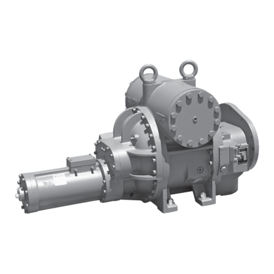
ROTARY SCREW COMPRESSORS
SGC 1913-2824, SGCB/H 3511-3519,
Original SGXB 3519-3524, SGXH 3519, and 4013-4021
This manual contains rigging, assembly, start-up, and maintenance
instructions. Read thoroughly before beginning installation. Failure
to follow these instructions may result in personal injury or death,
Check www.FrickCold.com for the latest version of this publication.
SGC/SGX
MODELS:
damage to the unit, or improper operation.
Form 070.650-IOM (JUL 2019)
INSTALLATION - OPERATION - MAINTENANCE
File:
SERVICE MANUAL - Section 070
Replaces:
070.650-IOM (AUG 2015)
Dist:
3, 3a, 3b, 3c
Advertisement
Table of Contents
Troubleshooting

Subscribe to Our Youtube Channel
Related Manuals for Frick SGC 1913


Summary of Contents for Frick SGC 1913
- Page 1 3, 3a, 3b, 3c SGC/SGX ROTARY SCREW COMPRESSORS MODELS: SGC 1913-2824, SGCB/H 3511-3519, Original SGXB 3519-3524, SGXH 3519, and 4013-4021 This manual contains rigging, assembly, start-up, and maintenance instructions. Read thoroughly before beginning installation. Failure to follow these instructions may result in personal injury or death, damage to the unit, or improper operation.
-
Page 2: Table Of Contents
070.650-IOM (JUL 19) SGC/SGX ROTARY SCREW COMPRESSOR Page 2 INSTALLATION - OPERATION - MAINTENANCE Contents General Information Operation Preface ................3 Operation and Start-Up Instructions ......35 Design Limitations ............3 Low Ambient Temperature Operation ......35 Job Inspection ..............3 Initial Start-Up ............... -
Page 3: General Information
It is important that these compressors are properly applied to an adequately controlled refrigerant or gas system. TRANSIT DAMAGE CLAIMS Consult your authorized Johnson Controls-FRICK represen- All claims must be made by consignee. This is an ICC tative for expert guidance in this determination. -
Page 4: Long Term Storage
A = JAN, B = FEB, C = MAR, D = APR, E = MAY, F = JUN, The standard Johnson Controls-FRICK Warranty for an G = JUL, H = AUG, K = SEP, L = OCT, M = NOV, N = DEC. -
Page 5: Preparing Compressor For Storage
• Balance pistons, located in the inlet end of the com- 5. Pump oil into the SM1. Johnson Controls-FRICK rec- pressor, reduce axial loads on the male axial bearings ommends break-in oil P/N 111Q0831809 for storage to increase bearing life. -
Page 6: Compressor Lubrication System
Provides an oil supply to hydraulically actuate the slide The rotors are made from the highest quality steel bar- valve and slide stop. stock or forgings to the exacting tolerances of FRICK de- signed high-efficiency rotor profiles. The four-lobed male • Provides oil pressure to the balance piston to help rotor (5 lobes on 408) is connects directly to the driver. - Page 7 2313 2317 Volumizer variable volume ratio control Refer to 2321 The FRICK compressor includes a method of varying the NS-7-11 2813 internal volume ratio to match the system pressure ratio. 2817 Control of the internal volume ratio eliminates the power...
- Page 8 070.650-IOM (JUL 19) SGC/SGX ROTARY SCREW COMPRESSOR Page 8 INSTALLATION...
-
Page 9: Installation
Refer to 090.020-M - FRICK Compressor Control Panel for additional information on set-point limits. SGCH 3511 and SGCB 3511 DWG# 534E0966 SGCH 3515 and SGCB 3515 DWG# 534E0971 For proper piping, also refer to the FRICK package manual, SGCH 3519 and SGCB 3519 DWG# 534E0972 070.610-IOM - RWF II Rotary Screw Compressor Units, Models 100 through 1080. SGXH 3519 and SGXB 3519/3524 DWG# 534E1405... - Page 10 REMOVAL REMOVAL 73.9 [2.91] 12.75 .502 138.0 [5.43] 50.09 1.972 49.71 1.957 SC-8 SM-1 57.150 2.2500 Ø 57.125 2.2490 34.0 [1.34] C MOUNTING HOLE VIEW A-A VIEW A-A PARTIAL VIEW SGC1913 PARTIAL VIEW SGC1913 Figure 3: Port locations, SGC 1913/1918...
- Page 11 [17.43] 211.8 296.0 584.2 105.9 609.6 494.5 992.4 1532.1 317.5 241.3 152.4 269.7 706.1 257.3 529.6 SGC1918 1.80 [8.34] [11.65] [23.00] [4.17] [24.00] [19.47] [39.07] [60.32] [12.50] [9.50] [6.00] [10.62] [27.80] [10.13] [20.85] Figure 3: Port locations, SGC 1913/1918 (continued)
- Page 12 070.650-IOM (JUL 19) SGC/SGX ROTARY SCREW COMPRESSOR Page 12 INSTALLATION Port Thread size (in.) Description 3/4-16 UNF-2B Manifold block 163.9 [6.45] MOUNTING FOOT straight THD O-ring pressure SD-1 Balance piston 3/4-16 UNF-2B SLIDE VALVE LINEAR SB-2 and inlet bear- straight THD O-ring TRANSMITTER ings 278.8 [10.98]...
- Page 13 SGC/SGX ROTARY SCREW COMPRESSOR 070.650-IOM (JUL 19) INSTALLATION Page 13 TE-1 SL-1 SV-1 114.3 [4.50] 177.8 [7.00] CAUTION CAUTION THIS EQUIPMENT HAS BEEN PRESSURIZED WITH NITROGEN GAS. TEMPORARY VALVES & GAUGES HAVE BEEN INSTALLED. CYLINDER ASSEMBLY UNDER HIGH SPRING LOAD. 1.
- Page 14 070.650-IOM (JUL 19) SGC/SGX ROTARY SCREW COMPRESSOR Page 14 INSTALLATION Port Thread size (in.) Description 163.9 [6.45] MOUNTING FOOT SD-1 3/4-16 UNF-2B Manifold block straight THD O-ring pressure SLIDE VALVE LINEAR Balance piston 3/4-16 UNF-2B TRANSMITTER SB-2 and inlet bear- 265.4 [10.45] 278.8 [10.98] straight THD O-ring...
- Page 15 SGC/SGX ROTARY SCREW COMPRESSOR 070.650-IOM (JUL 19) INSTALLATION Page 15 TE-1 170.2 [6.70] SL-1 SV-1 114.3 [4.50] 88.9 [3.50] 161 [6.34] 177.8 [7.00] CAUTION CAUTION THIS EQUIPMENT HAS BEEN PRESSURIZED WITH NITROGEN GAS. TEMPORARY VALVES & GAUGES HAVE BEEN INSTALLED. CYLINDER ASSEMBLY UNDER HIGH SPRING LOAD.
- Page 16 070.650-IOM (JUL 19) SGC/SGX ROTARY SCREW COMPRESSOR Page 16 INSTALLATION Port Thread size (in.) Description MOUNTING FOOT 1 1/16-12 UN-2B Manifold block 206.5 [8.13] straight THD O-ring pressure 197.1 [7.76] SD-1 Balance piston 1 1/16-12 UN-2B SB-2 and inlet bear- straight THD O-ring ings 341.9 [13.46]...
- Page 17 SGC/SGX ROTARY SCREW COMPRESSOR 070.650-IOM (JUL 19) INSTALLATION Page 17 TE-1 90.4 [3.56] 175.8 [6.92] SM-1 SC-8 SL-1 SV-1 13.2 [.52] 53.8 [2.12] MOUNTING FOOT 146.1 [5.75] PARTIAL VIEW SGC2813 90.4 [3.56] 175.8 [6.92] 168.4 [6.63] CAUTION CAUTION THIS EQUIPMENT HAS BEEN PRESSURIZED WITH NITROGEN GAS.
- Page 18 070.650-IOM (JUL 19) SGC/SGX ROTARY SCREW COMPRESSOR Page 18 INSTALLATION Port Thread size (in.) Description 1 1/16-12 UN-2B Manifold block 762 [30.00] 762 [30.00] 762 [30.00] DISTANCE REQUIRED FOR STRAINER REMOVAL 381 [15.00] straight THD O-ring pressure DISTANCE REQUIRED FOR 187.7 [7.39] STRAINER REMOVAL Balance piston...
- Page 19 SGC/SGX ROTARY SCREW COMPRESSOR 070.650-IOM (JUL 19) INSTALLATION Page 19 198.9 [7.83] TE-1 SL-1 SV-1 146.1 [5.75] 81 [3.19] 175.8 [6.92] 168.4 [6.63] CAUTION CAUTION THIS EQUIPMENT HAS BEEN PRESSURIZED WITH NITROGEN GAS. TEMPORARY VALVES & GAUGES HAVE BEEN INSTALLED. CYLINDER ASSEMBLY UNDER HIGH SPRING LOAD.
- Page 20 070.650-IOM (JUL 19) SGC/SGX ROTARY SCREW COMPRESSOR Page 20 INSTALLATION Port Thread size (in.) Description 762 [30.00] 762 [30.00] 1 1/16-12 UN-2B Manifold block DISTANCE REQUIRED FOR 381 [15.00] 187.7 [7.39] STRAINER REMOVAL straight THD O-ring pressure Balance piston 1 1/16-12 UN-2B INSTALL A SOLID 1/2-14 NPTF SB-2 and inlet bear-...
- Page 21 SGC/SGX ROTARY SCREW COMPRESSOR 070.650-IOM (JUL 19) INSTALLATION Page 21 241.6 [9.51] TE-1 SL-1 SV-1 SD-1 146.1 [5.75] SV-1 81 [3.19] SM-1 168.4 [6.63] 175.8 [6.92] SL-1 CAUTION CAUTION THIS EQUIPMENT HAS BEEN PRESSURIZED WITH NITROGEN GAS. TEMPORARY VALVES SC-8 &...
- Page 22 070.650-IOM (JUL 19) SGC/SGX ROTARY SCREW COMPRESSOR Page 22 INSTALLATION SC-7: SEAL WEEPAGE Port Thread size (in.) Note SB-2 3/4 - 14 NPTF SB-3 ⁄ ⁄ NPTF SC-3 ⁄ - 14 NPTF SC-4 ⁄ - 14 NPTF SC-5 ⁄ - 18 NPTF SC-6 ⁄...
- Page 23 SGC/SGX ROTARY SCREW COMPRESSOR 070.650-IOM (JUL 19) INSTALLATION Page 23 SC-7: SEAL Port Thread size (in.) Note WEEPAGE SB-2 ⁄ - 14 NPTF SB-3 ⁄ - 11 ⁄ NPTF SB-4 1 - 11 ⁄ NPTF SC-3 ⁄ - 14 NPTF SC-4 ⁄...
- Page 24 070.650-IOM (JUL 19) SGC/SGX ROTARY SCREW COMPRESSOR Page 24 INSTALLATION X - Mandatory ST-1: SUCTION TEMPERATURE SD-1: COALESCER BLEED/SUCTION PRESSURE connection SC-5: SUCTION PRESSURE SM-1: MAIN OIL INJECTION O - Optional connection SC-9: CLOSED THREAD SV-1: VAPOR INJECTION S - Service PRESSURE connection SC-9: CLOSED THREAD PRESSURE...
-
Page 25: Holding Charge And Storage
Page 25 HOLDING CHARGE AND STORAGE SGC/SGX compressors are pressure and leak tested at the Johnson Controls–FRICK factory and thoroughly evacuated and charged with dry nitrogen to ensure integrity during ship- ping and short term storage prior to installation. Keep all compressors in a clean, dry location to prevent cor- rosion damage. -
Page 26: Customer Connections
100 cSt must not be exited. rest on the support bracket and the motor mount. FRICK compressor oils are recommended — refer to In any screw compressor installation, support suction and 160.802-SPC. Coolware provides FRICK oil properties and... - Page 27 SGC/SGX ROTARY SCREW COMPRESSOR 070.650-IOM (JUL 19) INSTALLATION Page 27 Balance Shaft Seal Piston Capacity Increase Increase Decrease Capacity Decrease Linear Transmitter Slide Stop Slide Valve For Capacity Indication (Internal Oil Feed: 193 - 283 models) Figure 16: Balance piston location and capacity/Vi manifold designations (193 - 283) SB-2 Balance Inlet End...
- Page 28 070.650-IOM (JUL 19) SGC/SGX ROTARY SCREW COMPRESSOR Page 28 INSTALLATION OUTLET END BALANCE INLET END PISTON MALE SIDE MALE SIDE INLET END OUTLET END FEMALE SIDE FEMALE SIDE Figure 18: Balance piston and squeeze film damper locations (408 model)
-
Page 29: Compressors With Squeeze Film Damper (Sfd)
55 psi below discharge pressure when SV < 65%. Contact requirements. the factory for more specific configuration information. FRICK CoolWare can calculate oil flows, pressure and tem- In the case that application and/or operating conditions perature required. Add all nominal operation conditions, change, review the BPR settings. Configuration changes including SB-3 and SB-4 oil pressure requirements, to your may be necessary, in which case, contact engineering. -
Page 30: Oil Filter(S)
COMPRESSOR/MOTOR COUPLING REQUIREMENTS SGC/SGX compressors are arranged for direct motor drive and require a flexible drive coupling to connect the compressor to the motor. If you are using the Johnson Controls – FRICK motor mount,... -
Page 31: Coupling Alignment Requirements (Foot Mounted Only)
Set magnetic center correctly on the sleeve bearing operation. Connect to +/- and signal as shown in the wiring motors. diagram in Figure 22. Refer to FRICK Compressor Control Panel 090.040-O for instructions for calibration procedure. Set up the minimum distance between compressor shaft and motor shaft to allow for seal removal (see Outline drawings). -
Page 32: Directional Control Valves
COMPRESSOR TOP VIEW (INCREASE VI) YY3 YY4 (DECREASE VI) (UNLOAD) YY1 YY2 (LOAD) COMPRESSOR TOP VIEW Valve 2 (INCREASE VI) YY3 YY4 (DECREASE VI) (UNLOAD) YY1 YY2 (LOAD) Figure 26: Hydraulic Schematic, SGC 1913 - 2824, SGC 3511 - 3524... - Page 33 SGC/SGX ROTARY SCREW COMPRESSOR 070.650-IOM (JUL 19) INSTALLATION Page 33 DELETE (NC) FOR DELETE (NC) FOR DELETE (NC) FOR DELETE (NC) FOR HIGH STAGE HIGH STAGE BOOSTER BOOSTER APPLICATIONS APPLICATIONS APPLICATIONS APPLICATIONS 1541 1541 1542 1542 1543 3/8 OD SS 3/8 OD SS 1544 INCREASE...
-
Page 34: Volumizer Volume Ratio Control
070.650-IOM (JUL 19) SGC/SGX ROTARY SCREW COMPRESSOR Page 34 INSTALLATION VOLUMIZER VOLUME RATIO CONTROL Open valve at SC3 Open valve at SC4 Compressor Vi increase: The volume ratio Vi is increased when MSS solenoid valve YY3 is energized and oil flows from the oil manifold through valve ports P and A to compressor port SC3, enters the increase side of the cylinder and overcomes the decreased spring tension. Simultaneously, oil flows from SC4 port through valve ports B and T to compressor suction. -
Page 35: Operation And Start-Up Instructions
Page 35 Operation OPERATION AND START-UP INSTRUCTIONS INITIAL START-UP FRICK SGC/SGX Rotary Screw Compressors are components Prior to the start-up, the pre-start check must be in an integrated system. As such, the compressor requires accomplished. See Forms section for Checklist. -
Page 36: Maintenance
070.650-IOM (JUL 19) SGC/SGX ROTARY SCREW COMPRESSOR Page 36 MAINTENANCE Maintenance GENERAL INFORMATION 5. Protect the compressor during long periods of shut- This section provides instructions for normal maintenance, down. If the compressor sits for long periods without run- a recommended maintenance program, and troubleshooting ning, it is advisable to evacuate to low pressure and charge and correction guides. -
Page 37: Maintenance Schedule
SGC/SGX ROTARY SCREW COMPRESSOR 070.650-IOM (JUL 19) MAINTENANCE Page 37 Maintenance schedule Recommended schedule for SGC/SGX FRICK rotary screw compressor preventive maintenance operations. Frequency or hours of operation (maximum) Maintenance Change Oil As Directed By Oil Analysis Oil Analysis Every 6 Months... -
Page 38: Vibration Analysis
3. Excessively high discharge pressure. 1. Only use FRICK oil or high quality oils approved by Johnson 4. Excessively high or low temperature coolant to the oil Controls - FRICK for your application. -
Page 39: Troubleshooting The Sgc Compressor
• Piston Seals worn out/damaged. Contact Johnson Controls - FRICK Service for assistance. Notice Unless the Service Technician has been certified by Johnson Controls – FRICK to rebuild our compressors, troubleshoot- ing the compressor is limited to identifying the probable cause. If a mechanical problem is suspected contact Johnson Controls –... -
Page 40: Capacity Linear Transmitter Replacement - Slide Valve
070.650-IOM (JUL 19) SGC/SGX ROTARY SCREW COMPRESSOR Page 40 MAINTENANCE TROUBLESHOOTING GUIDE The linear transmitter, with hermetic enclosure is based (CONTINUED) on the inductive measuring principle. It features removable CAPACITY LINEAR TRANSMITTER REPLACEMENT - electronics (from the sensor well) eliminating the need to SLIDE VALVE evacuate the compressor for replacement. -
Page 41: Forms
SGC/SGX ROTARY SCREW COMPRESSOR 070.650-IOM (JUL 19) FORMS Page 41 Forms FORMS ROTARY SCREW COMPRESSOR OPERATING LOG SHEET... -
Page 42: Compressor Prestart Checklist
__ DO NOT energize compressor drive motor! Only authorized Factory Field Service Technicians are to perform this. Summary: Ensure the above items are completed for when the FRICK Field Service Supervisor arrives. Ensure there is an uncoupled compressor drive unit (to verify motor rotation and alignment) and energized oil heaters with the oil at the proper standby temperatures. -
Page 43: Drive Train Alignment
SGC/SGX ROTARY SCREW COMPRESSOR 070.650-IOM (JUL 19) FORMS Page 43 DRIVE TRAIN ALIGNMENT Ambient Temperature at Time of Alignment _______ Oil Separator Temperature at Time of Alignment ________ Motor Coupling Type ___________ Size ___________ Distance Between Coupling Hub Faces __________ Soft Foot Check OK as Found Shimming Required... -
Page 44: Vibration Data Sheet
070.650-IOM (JUL 19) SGC/SGX ROTARY SCREW COMPRESSOR Page 44 FORMS VIBRATION DATA SHEET Date: __________________________________________ Sales Order Number: ________________________________ End User: _______________________________________ Installing Contractor: ________________________________ Address: __________________________________________ Service Technician: __________________________________ Equipment ID (As in Microlog): ____________________ Compressor Serial Number: __________________________ Unit Serial Number: _________________________________ National Board Number: _____________________________ Running Hours: _____________________________________... - Page 45 SGC/SGX ROTARY SCREW COMPRESSOR 070.650-IOM (JUL 19) INDEX Page 45 Index accumulator, 3 identification data plate, 3 seal life, 5 allowable flange loads, 26 installation, 9 seal well, 5, 6, 7 angular-contact bearings, 5 insulated, 35 serial number, 3 ASHRAE, 3 shaft alignment, 40 shaft seal housing, 5 shipping gauges, 25...
- Page 46 Johnson Controls Supersedes: 070.650-IOM (2015-08) 100 Cumberland Valley Avenue Subject to change without notice Waynesboro, PA 17268-1206 USA Published in USA • 07/19 • PDF Phone: 717-762-2121 • FAX: 717-762-8624 www.jci.com/FRICK © 2019 Johnson Controls Int’l PLC - ALL RIGHTS RESERVED...
Need help?
Do you have a question about the SGC 1913 and is the answer not in the manual?
Questions and answers