Advertisement
Check the Supplied Items
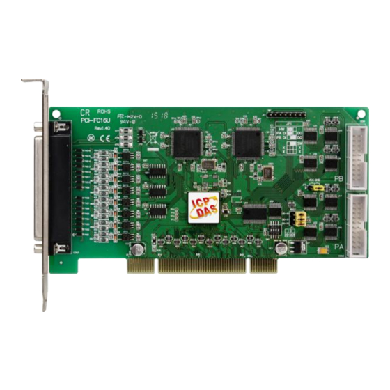
The shipping package includes the following items:
PCI-FC16U
1
PCI-FC16U Quick Start Guide
Website: http:// www.icpdas.com.tw
Software Utility CD
(V6.2 or later)
E-Mail: service@icpdas.com , service.icpdas@gmail.com
For PCI-FC16U
English/Oct. 2015/Version 1.1
Quick Start Guide
(This Document)
ICP DAS CO., LTD.
CA-4002 D-Sub
Connector
Advertisement
Table of Contents

Related Manuals for ICP DAS USA PCI-FC16U


Summary of Contents for ICP DAS USA PCI-FC16U
- Page 1 Check the Supplied Items The shipping package includes the following items: Quick Start Guide PCI-FC16U Software Utility CD CA-4002 D-Sub (This Document) (V6.2 or later) Connector PCI-FC16U Quick Start Guide ICP DAS CO., LTD. Website: http:// www.icpdas.com.tw E-Mail: service@icpdas.com , service.icpdas@gmail.com...
- Page 2 Installing the Windows Driver The UniDAQ driver supports Windows 2000 and 32/64-bit versions of Windows XP/2003/2008/7/8. The driver installation package for PCI-FC16U board can be found on the companion CD-ROM, or can be obtained from the ICP DAS FTP web site.
- Page 3 Software Programmable DIO-S0 Note that the DIO-S1 and DIO-S2 jumpers are not used when the DIO-S0 jumper is set to “Software Program” Mode. Refer to PCI-FC16U User Manual for more detail information. PCI-FC16U Quick Start Guide ICP DAS CO., LTD.
- Page 4 Step 2: Remove all the covers from the computer. Step 3: Select an unused PCI slot. Step 4: Carefully insert the PCI-FC16U board into the PCI slot and secure the board in place. Step 5: Replace the covers on the computer.
- Page 5 Pin Assignments PCI-FC16U Quick Start Guide ICP DAS CO., LTD. Website: http:// www.icpdas.com.tw E-Mail: service@icpdas.com , service.icpdas@gmail.com...
- Page 6 Wiring for the Digital Input/Output Test: Step 1: Keep set the JP1 jumper to “SW” position (See Section 4 Jumper Settings). Step 2: Connect the CON1 to CON2 on the PCI-FC16U board using the CA-2002 cable (optional). CA-2002 Cable ...
- Page 7 Step 4: Confirm that the PCI-FC16U board has been successfully installed in the Host system. Note that the device numbers start from 0. Step 5: Click the “TEST” button to start the test. Step 6: Check the results of the Digital Input/Output functions test.
- Page 8 6. The DI indicators will turn red when the corresponding DO channels 0, 2, 4 and 6 are ON. Related Information PCI-FC16U Series Board Product Page: http://www.icpdas.com/root/product/solutions/pc_based_io_board/pci/pci-fc16u. html CA-2002 Product Pages (optional): http://www.icpdas.com/products/Accessories/cable/cable_selection.htm UniDAQ Documentation and Software: CD:\NAPDOS\PCI\UniDAQ\ http://ftp.icpdas.com/pub/cd/iocard/pci/napdos/pci/unidaq/...
Need help?
Do you have a question about the PCI-FC16U and is the answer not in the manual?
Questions and answers