Table of Contents
Advertisement
Available languages
Available languages
Quick Links
Kichler® is a registered trademark of
The L.D. Kichler Co. All Rights Reserved.
ATTACH YOUR RECEIPT HERE
Serial Number
Questions, problems, missing parts? Before returning to your retailer, call our
customer service department at 1-800-554-6504, 8 a.m. - 4:30 p.m, EST, Monday - Friday.
Purchase Date
1
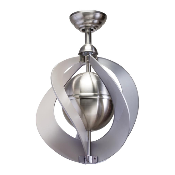
ITEM #0831588
CEILING FAN
MODEL #35162
Français p. 13
Advertisement
Table of Contents

Related Manuals for Kichler Lighting 35162


Summary of Contents for Kichler Lighting 35162
- Page 1 ITEM #0831588 CEILING FAN Kichler® is a registered trademark of The L.D. Kichler Co. All Rights Reserved. MODEL #35162 Français p. 13 ATTACH YOUR RECEIPT HERE Serial Number Purchase Date Questions, problems, missing parts? Before returning to your retailer, call our...
-
Page 2: Package Contents
PACKAGE CONTENTS PART DESCRIPTION PART DESCRIPTION Hanging Bracket Upper Fan Blade Assembly Down Rod Lower Fan Blade Assembly Canopy Fan Blade Canopy Cover Upper Rectangular Washer Motor Coupling Cover Lower Rectangular Washer Motor Assembly... -
Page 3: Hardware Bag
PACKAGE CONTENTS HARDWARE BAG BALANCE KIT BAG REMOTE CONTROL Hanging bracket Screw Hanging bracket Washer Remote Control Balance Kit Balance Kit Wire Connector Remote Control Holder Blade Screw Wood Screw Receiver Lag Screw Battery Wood Screw Flat Washer + Spring Washer Wire Connector SAFETY INFORMATION Please read and understand this entire manual before attempting to assemble, operate or install the... - Page 4 WARNING (continued) • Make sure the installation site you choose allows a minimum of 7 feet from the floor to the end of the blades. • To reduce the risk of fire or electrical shock, do not use this fan with any solid state fan speed device or variable speed control.
- Page 5 ASSEMBLY INSTRUCTIONS 1. Secure the hanging bracket (A) to the ceiling outlet Outlet Box box using hanging bracket screws and hanging bracket washers. Important: If attaching the fan to a sloped ceiling, make sure open end of mounting bracket is installed facing the roof.
- Page 6 ASSEMBLY INSTRUCTIONS 4. Pass the clevis pin through the down rod (B) and coupling found on the motor assembly (F) and secure with the hair pin. Tighten set screws found on the coupling on the motor assembly (F). Hair Pin Clevis Pin Coupling 5.
- Page 7 ASSEMBLY INSTRUCTIONS 7. Wiring the fan per wiring diagram and securely connect wires with wire connectors: • Connect WHITE wire marked AC IN N from the fan to WHITE wire marked TO MOTOR N from the receiver. • Connect BLACK marked AC IN L wire from the fan to BLACK marked TO MOTOR L wire from the receiver.
- Page 8 ASSEMBLY INSTRUCTIONS 8. In order to use the remote control the dip switches Receiver must match on both the remote control and the receiver. Make sure they both have the same configuration. Remove the battery cover from the remote control. Slide dip switches up or down using a small screw driver (not included).
- Page 9 ASSEMBLY INSTRUCTIONS 11. Remove shipping retainer from the motor assembly (F) before assembling the fan blades in the next step. Shipping Retainer 12. Raise fan blade (I) to the upper fan blade assembly (G) making sure the holes line up on both the fan blade (I) and the upper fan blade assembly (G).
-
Page 10: Fcc Warning
ASSEMBLY INSTRUCTIONS 13. Install remote control holder onto wall with wood Remote Control Holder screws provided. Wood Screw FCC WARNING Warning: Changes or modifications to this unit not expressly approved by the party responsible for compliance could void the user’s authority to operate the equipment. This equipment has been tested and found to comply with the limits for a Class B digital device, pursuant to part 15 of the FCC rules. -
Page 11: Operation
OPERATION Remove remote battery door, connect 9V battery (included) with plug pressing the battery inside and replace the battery door. Fan control : Low speed Medium speed High speed To turn off the fan This remote control (M) has a memory function. The remote control (M) stores the fan speed when the fan is turned off. -
Page 12: Warranty
IMPLIED, INCLUDING THOSE OF MERCHANTABILITY, FITNESS FOR ANY PARTICULAR PURPOSE OR INFRINGEMENT. ORIGINAL PURCHASER SHALL IN NO EVENT BE ENTITLED TO, AND KICHLER LIGHTING SHALL NOT BE LIABLE FOR, INDIRECT, SPECIAL, INCIDENTAL OR CONSEQUENTIAL DAMAGES OF ANY NATURE, INCLUDING, BUT NOT LIMITED TO LOSS OF PROFIT, PROMOTIONAL AND/OR MANUFACTURING EXPENSES, OVERHEAD, INJURY TO REPUTATION AND/OR LOSS OF CUSTOMERS. - Page 13 ARTICLE #0831588 VENTILATEUR DE PLAFOND Kichler® est une marque déposée de The L.D. Kichler Co. Tous droits réservés. MODÈLE #35162 JOIGNEZ VOTRE REÇU ICI Numéro de série Date d’achat Des questions, des problèmes, des pièces manquantes? Avant de retourner le produit à...
-
Page 14: Contenu De L'emballage
CONTENU DE L’EMBALLAGE PIÈCE DESCRIPTION QTÉ PIÈCE DESCRIPTION QTÉ Support de suspension Support supérieur de montage des pales Tige Support inférieur de montage des pales Pavillon Pale du ventilateur Cache du pavillon Rondelle rectangulaire supérieure Cache raccord du moteur Rondelle rectangulaire inférieure Ensemble moteur... -
Page 15: Quincaillerie Incluse
QUINCAILLERIE INCLUSE SACHET DE QUINCAILLERIE TÉLÉCOMMANDE ENSEMBLE D'ÉQUILIBRAGE Vis du support de suspension Rondelle du support de suspen TÉLÉCOMMANDE Ensemble d'équilibrage Capuchon de connexion Support de la télécommande Vis de pale Vis à bois Récepteur Récepteur Pile Tire-fond Vis à bois Rondelle plate + rondelle ressort Capuchon de connexion CONSIGNES DE SÉCURITÉ... -
Page 16: Instructions Pour L'assemblage
(suite) AVERTISSEMENT • Assurez-vous que le site d'installation choisi offre une hauteur minimum de 2,13 m (7 pi) entre le sol et le dessous des pales. • Pour réduire les risques d'incendie ou de choc électrique, n'utilisez pas ce ventilateur avec une commande de vitesse à... - Page 17 INSTRUCTIONS POUR L'ASSEMBLAGE Boîte de sortie 1. Fixez le support de suspension (A) à la boîte de sortie du plafond à l'aide des vis et des rondelles fournies avec le support de suspension. Important : Si vous fixez le ventilateur sur un plafond incliné, assurez-vous que l'extrémité...
- Page 18 INSTRUCTIONS POUR L'ASSEMBLAGE 4. Faites passer la clavette à travers la tige (B) et le raccord situé sur l'ensemble moteur (F) et fixez à l'aide de la goupille de verrouillage. Serrez les vis de réglage situées sur le raccord de l'ensemble moteur Goupille (F).
- Page 19 INSTRUCTIONS POUR L'ASSEMBLAGE Boîte de sortie 7. Réalisez le câblage du ventilateur conformément au schéma de câblage et connectez fermement les fils à l'aide des connecteurs de fils : • Connectez le fil BLANC marqué AC IN N provenant du ventilateur au fil BLANC marqué TO MOTOR N provenant du récepteur.
- Page 20 INSTRUCTIONS POUR L'ASSEMBLAGE 8. Pour utiliser la télécommande les commutateurs DIP Récepteur doivent correspondre à la fois sur la télécommande et le récepteur. Assurez-vous qu'ils ont tous deux la même configuration. Retirez le couvercle de la batterie de la télécommande. Faites glisser les commutateurs DIP haut ou le bas à...
- Page 21 INSTRUCTIONS POUR L'ASSEMBLAGE 11. Retirez de l’ensemble moteur (F) le dispositif de retenue prévu pour le transport, avant de monter les pales du ventilateur à l’étape suivante. Dispositif de retenue Placez une pale de ventilateur (I) contre le support supérieur de montage des pales (G) en prenant soin d’aligner les trous de la pale (I) avec ceux du support supérieur de montage des pales (G).
-
Page 22: Avertissement De La Fcc
INSTRUCTIONS POUR L'ASSEMBLAGE 13.Installez le support de la télécommande sur le mur Support de la télécommande avec les vis à bois fournies. Vis à bois AVERTISSEMENT DE LA FCC Avertissement : tous changements ou modifications apportés à ce produit et non expressément approuvés par l'autorité... -
Page 23: Entretien
FONCTIONNEMENT Retirez la porte du compartiment de la pile, introduisez une pile de 9 V (fournie) et remettez la porte en place. Réglage du ventilateur : vitesse lente vitesse moyenne vitesse rapide Pour arrêter le ventilateur Cette télécommande (M) possède une fonction mémoire. La télécommande (M) garde en mémoire la vitesse du ventilateur quand celui-ci est éteint. -
Page 24: Garantie
OU IMPLICITE, Y COMPRIS TOUTE GARANTIE DE QUALITÉ MARCHANDE, D'ADÉQUATION À UN USAGE PARTICULIER OU DE NON-CONTREFAÇON. L'ACHETEUR INITIAL NE PEUT EN AUCUN CAS PRÉTENDRE À INDEMNISATION POUR, ET KICHLER LIGHTING NE PEUT ÊTRE TENU RESPONSABLE DES DOMMAGES INDIRECTS, PARTICULIERS, ACCESSOIRES OU CONSÉCUTIFS DE TOUTE NATURE, Y COMPRIS MAIS SANS S'Y LIMITER LA PERTE DE PROFIT, LES DÉPENSES PROMOTIONNELLES...
Need help?
Do you have a question about the 35162 and is the answer not in the manual?
Questions and answers