
Related Manuals for Fortis RC-400A


Summary of Contents for Fortis RC-400A
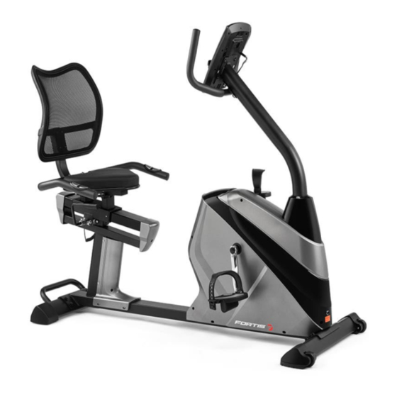
- Page 1 AUTOMATIC VARIABLE RESISTANCE MAGNETIC FLYWHEEL RECUMBENT BIKE (RC-400A) FSARCB400AA...
-
Page 2: Table Of Contents
Contents Safety & warnings Overview Assembly Operation Programs Notes... -
Page 3: Safety & Warnings
SAFETY & WARNINGS Read all of the instructions in this guide before using this product. Retain this guide for future reference. Do not skip, substitute or modify any steps or procedures in this guide, as doing so could result in personal injury or product damage. •... - Page 4 • Do not place fingers or any other objects into moving parts of the exercise equipment. • After exercising, turn the adjusting Knob to increase tension so the pedals will not rotate freely and possibly hurt someone while bike is not in use. •...
-
Page 5: Overview
OVERVIEW... - Page 6 Part List Description Description Console Main frame Screw M5 x 10 x Φ10 Pedal L/R Mid sensor wire 1 Front stabilizer Handlebar post Hex bolt M8 x 20 x S13 Washer d8 x Φ20 x 2 Handlebar Arc washer d8 x ФΦ20 x 2 x Front stabilizer cap L/R Screw ST ST4.2 x 25 Φ8 Screw M8 x 16 x S6...
- Page 7 Cap Φ12 x 11 x Φ3 Foam grip Φ23 x 5 x 500 Right handlebar cover Nut M8 x H16 x S13 Screws ST4.2 x 16 x Φ8 Left handlebar cover Rear stabilizer Handle pulse wire Handlebar cover t3 x 38 x Rear stabilizer cap-right Adjustable foot Bolt M8 x 47 x 20 x H5...
- Page 8 Power wire Magnetic board axle Chain cover L/R Magnetic board Screw ST ST3 x 10 x Φ5.6 Crank hole cap Shaft Ring d17 Tension spring washer Magnet seat 45.5 x 130 x 10.5 Bearing 6203-2RS Square magnet 39 x 24.5 x 10 Bushing Φ22 x Φ17.1 x 5.5 Hex boltM6 x 45 x S10 Hex bolt 16mm...
-
Page 9: Assembly
ASSEMBLY Step 1 Remove the x4 Hex Bolts (16) and x4 Washers (17) from the Mounting Plate (68) using the Wrench (65). Set the Hardware and the Mounting Plate (68) aside. - Page 10 Step 2 Use the Wrench (65) to unscrew the x8 Hex Bolts (16) and take off the x8 Spring Washers (8) and Washers (17). Set them aside for stabilizer attachment. Assemble the Front Stabilizer (15) on the Main Frame (13) with x4 Hex Bolts (16), x4 Spring Washers (8) and x4 Washers (17).
- Page 11 Step 3 Use the Allen Wrench (66) to unscrew the x4 Screws (9), x4 Spring Washers 8mm (8) and x4 Arc Washers (7) from the Handlebar Post (5). Slide the Post Cover (10) onto the Handlebar Post (5) and connect the Mid Sensor Wire 1 (4) at the bottom of the Handlebar Post (5) with the Mid Sensor Wire 2 (12) coming out of the Main Frame (13).
- Page 12 Step 4 Use the Allen Wrench (66) to unscrew the x2 Screws (9), x2 Spring Washers (8) and x2 Arc Washers (7) from the Handlebar Post (5). Attach the Handlebar (6) to the Handlebar Post (5) with x2 Screws (9), x2 Spring Washers (8) and x2 Arc Washers (7).
- Page 13 Step 5 Use the Allen Wrench (67) to unscrew x2 Screws (42), x2 Washers (41) and x2 Arc Washers (46) from the Adjustable Handle (47). Attach the Adjustable Handle (47) to the Adjustment lever shaft (44) with the screws and washers you just took off the Adjustable Handle (47). Use the Allen Wrench (67) to secure.
- Page 14 Step 6 Use the Allen Wrench (66) to unscrew the 4 Bolts (69), x4 Spring Washers (8) and x4 Washers (17) from the Seat Slider (35). Attach the Seat Post (60) to the Seat Slider (35) with x4 Bolts (69), x4 Spring Washers (8) and x4 Washers (17) Use the Allen Wrench (66) to unscrew the x4 Screws (9) and x4 Washers (17) from the Seat (62).
- Page 15 Step 7 Use the Wrench (65) to unscrew the x4 Screws (63), x4 Washers (41) and x4 Washers (40) from the Back Pad (64). Attach the Back Pad (64) to the Seat Post (60) with 4 Screws (63), x4 Washers (41) and x4 Washers (40). Secure with Wrench (65). Attach the Handlebar (49) to the Seat Post (60) with x2 Bolts (55), x2 Washers (17), x2 Spring Washers (8), x2 Nuts (51) and Handlebar Cover (54).
- Page 16 Step 8 Unscrew the x4 screws (2) in the back of the Console (1) with Wrench (65) and set aside. Connect the Console Wire (1a) with the Mid Sensor Wire 1 (4). Push the wires down into the Handlebar Post (5), so they don’t get pinched. Attach the Console (1) to the Handlebar Post (5) with x4 Screws (2).
-
Page 17: Operation
OPERATION 1. Turn on the computer Plug in one end of the adaptor to a wall outlet and connect the other end to the computer. The computer will beep and enter into Manual mode. 2. Program select and value setting •... - Page 18 • SPEED: Displays your workout speed value in KM/MILE per hour. • CALORIES: Your computer will estimate the cumulative calories burned at any given time during your workout. • PULSE: Your computer displays your pulse rate in beats per minute during your workout.
- Page 19 4. Key Function There are 6 button keys and the function description as follows: START/STOP key: • Quick Start function: Allows you to start the computer without selecting a program. Manual workout only. Time automatically begins to count up from zero •...
-
Page 20: Programs
PROGRAMS P1: Manual program User can start exercise by pressing START/STOP key. The default resistance level is 5. Users may exercise in any desirous of resistance level (Adjusting by UP/DOWN keys during the workout) with a period of time or a number of calories or a certain distance. Use UP/DOWN keys to select the MANUAL (P1) program. - Page 21 The TIME will flash and you can press UP or DOWN keys to setting your exercise TIME. Press ENTER key to confirm your desired TIME. The DISTANCE will flash and you can press UP or DOWN keys to setting your target DISTANCE.
- Page 22 P18 - P22: Heart Rate Control Programs • P18 is the 55% Max H.R.C. - - Target H.R. = (220 – AGE) x 55% • P19 is the 65% Max H.R.C. - - Target H.R. = (220 – AGE) x 65% •...
- Page 23 The computer will show the test results of FAT PERCENT, BMI and BMR. Use UP/DOWN keys to select the BODY FAT (P23) program. Press the ENTER key to enter your workout program. The HEIGHT will flash and you can press UP or DOWN keys to set your HEIGHT. Press ENTER key to confirm your HEIGHT.
- Page 24 LCD Workout Graphics Program Display Program Display Manual Steps Rolling Hill Valley Fat Burn Mountain Ramp Internals Random Fartlek Plateau Precipice User 1 User 2 User 3 User 4 H.R.C.
- Page 25 H.R.C. H.R.C. Target H.R.C. H.R.C. Body Fat (Stop Mode)
- Page 26 Error Messages E1 (ERROR 1): • Normal state: During workout, when the monitor did not get the count signal from the gear motor more than 4 seconds and check under successive 3 times then the LCD will show E1. • Power on state: The gear motor will return to zero automatically, when the signal of motor cannot be detected for more than 4 seconds then the gear motor’s driver will be cut off immediately and show the E1 on the LCD display.
-
Page 27: Notes
NOTES... - Page 28 Need more information? We hope that this user guide has given you the assistance needed for a simple set-up. For the most up-to-date guide for your product, as well as any additional assistance you may require, head online to help.kogan.com...
Need help?
Do you have a question about the RC-400A and is the answer not in the manual?
Questions and answers