Table of Contents
Advertisement
Quick Links
AVD Series
Installation Manual
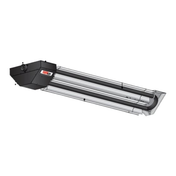
The AVD Series Infrared Tube Heater is a negative pressure, two-stage radiant heater system. This
manual provides specific information related to the AVD Series model. All persons involved with the
installation, operation and maintenance of the heater system must read and understand the information
in this manual.
Improper installation, adjustment, alteration, service or maintenance can cause
property damage, injury or death. Read the installation, operation and maintenance
instructions thoroughly before installing or servicing this equipment.
This heater must be installed and serviced by trained gas installation and service
personnel only. Failure to comply could result in personal injury, asphyxiation, death,
fire or property damage.
Do not store or use gasoline or other flammable vapors and liquids in the vicinity of
this or any other appliance.
In locations used for the storage of combustible materials, signs must be posted to
specify the maximum permissible stacking height to maintain the required clearances
from the heater to the combustibles. Signs must either be posted adjacent to the
heater thermostats or in the absence of such thermostats, in a conspicuous location.
Not for residential use! Do not use this heater in the home, sleeping quarters,
attached garages, etc. Installation of a commercial tube heater system in residential
indoor spaces may result in property damage, serious injury, asphyxiation or death.
For Your Safety
If you smell gas:
• Do not try to light any appliance.
• Do not touch any electrical switch.
• Do not use any phone in your building. • If you cannot reach your gas supplier, call the fire department.
WARNING
!
• Immediately call your gas supplier from a neighbor's phone.
• Follow the gas supplier's instructions.
Keep these instructions for future reference.
LIOAVD-8/10 (DRP)
Advertisement
Table of Contents

Related Manuals for Detroit Radiant Products AVD Series


Summary of Contents for Detroit Radiant Products AVD Series
- Page 1 AVD Series Installation Manual The AVD Series Infrared Tube Heater is a negative pressure, two-stage radiant heater system. This manual provides specific information related to the AVD Series model. All persons involved with the installation, operation and maintenance of the heater system must read and understand the information in this manual.
-
Page 2: Table Of Contents
Series Introduction • Table of Contents Contents 1.0 Introduction ............. . 3 Overview . -
Page 3: Introduction
Refer to page 44 for a list of the kit contents for your Series heater. Materials not included in the heater kit contents (e.g., screws, vent material, terminals, etc.) are the responsibility of the installer. Notify your product representative or Detroit Radiant Products of any discrepancy or missing kit contents prior to installing unit. -
Page 4: Safety Labels And Their Locations
Contact Detroit Radiant Products or an authorized dealer for Clearance Safety Limit Signs or for Clearance Safety Limit Tags (one tag is provided with each heater). - Page 5 Series Introduction • Safety Labels and Their Locations AVD Series Internal Block Wiring Diagram LINE VOLTAGE HIGH FIRE LOW FIRE NEUTRAL 120VAC 60Hz 24VAC (FIELD SUPPLIED) LOW FIRE HIGH FIRE RELAY RELAY BLOWER MOTOR 120V/24V TRANSFORMER PRESSURE SWITCH DIAGNOSTIC LIGHT...
-
Page 6: Safety
Series Safety • Warning Symbols Safety WARNING Improper installation, adjustment, alteration, service or maintenance can cause property damage, serious injury or death. Read and understand, the installation, operating and maintenance instructions thoroughly before installing or servicing this equipment. Only trained, qualified gas installation and service personnel may install or service this equipment. -
Page 7: Applications
Series Safety • Applications • Standards, Certifications and Regulations Applications This is not an explosion proof heater. No tube heater may be used in a Class 1 or Class 2 Explosive Environment. Consult your local fire marshall, insurance carrier and other authorities for approval if the proposed installation is in question. -
Page 8: Clearance To Combustibles
Series Safety • Clearance to Combustibles Clearance to Combustibles WARNING Placement of explosive objects, flammable objects, liquids and vapors close to the heater may result in explosion, fire, property damage, serious injury or death. Do not store or use explosive objects, liquids and vapors in the vicinity the heater. - Page 9 Series Safety • Clearance to Combustibles WARNING Failure to comply with the stated clearances to combustibles may result in personal injury, property damage and/or death. Failure to mount the appliance level may result in personal injury, property damage and/or death. Chart 2.1 •...
-
Page 10: Installation
Series Installation • Design Considerations and Prechecks Installation WARNING Improper installation, adjustment, alteration, service or maintenance can cause property damage, serious injury or death. Read and understand, the installation, operating and maintenance instructions thoroughly before installing or servicing this equipment. Only trained, qualified gas installation and service personnel may install or service this equipment. -
Page 11: Recommended Mounting Heights And Coverages
Factory recommended mounting heights are listed as a guideline. If infrared heaters are mounted too low or too high, they may result in discomfort or lack of heat. Detroit Radiant Products Company generally recommends observing the recommended mounting heights to optimize comfort conditions. However, certain applications such as spot heating, freeze protection, or very high ceilings may result in the heaters being mounted outside of the factory recommended mounting heights. -
Page 12: Heater Packaging
103 lbs. AVD-80 [N,P] 107” 103 lbs. NOTE: AVD Series heater ships as two packages; burner box and tube & reflector package. Shipping Dimensions: B = Burner Box (15#) & (31.5”L x 17.5”W x 15.5”H) T = Large Tube Box (88#) & (91”L x 31”W x 14”H) -
Page 13: Heater Assembly
Series Installation • Heater Assembly Heater Assembly Assembly prior to hanging: With this method, the use of two saw horses or a raised table or bench surface is beneficial (the emitter assembly box may also be used). Lay the emitter assembly (TP-6082) across the horses or bench with the exchanger connection hanging bracket (TP-6079) extended out over the edge (See Figure 3.3) NOTE: Use of the foam shipping blocks will help protect the emitter coating. -
Page 14: Preparing Points For Hanging
Series Installation • Heater Assembly • Preparing Points for Hanging Figure 3.4 • Final Heater Assembly Install reflector angle limit brackets Preparing Points for Hanging Transfer the heater’s three hanging locations to the ceiling where the unit is to be installed and mark hanging points. - Page 15 Series Installation • Preparing Points for Hanging • Hanging Types Figure 3.5 • Hanging Types Concrete Wood Beam Beam Screw Hook Support Support Blocking Blocking S-Hook and #1 Double-Loop Chain Beam Clamp Beam Clamp I-Beam I-Beam Threaded Rod and S-Hook and #1 Turnbuckle Double-Loop Chain Turnbuckle...
-
Page 16: Hanging Pre-Assembled Unit
Series Installation • Hanging Pre-Assembled Unit Hanging Pre-Assembled Unit When hanging the pre-assembled unit, special attention must be paid to the reflectors to keep from damaging or changing the 45° angle. Raise the assembled unit from assembly station to prepared hanging location. NOTE: This can be done manually or with a winch system. - Page 17 Series Installation • Hanging Pre-Assembled Unit • Final Check List Figure 3.7 • Hanging the Heater (Side View) 13.25” 81” 6.25” 12-18” 12-18” Mount Heater Level - Side to Side - TP-82 (typ. 4) set at 45° from horizontal. Figure 3.8 •...
-
Page 18: Venting
Series Installation • Venting Venting WARNING Insufficient ventilation and/or improperly sealed vents may release gas into the building which could result in health problems, carbon monoxide poisoning or death. Improper venting may result in fire, explosion, injury or death. Seal vent pipes with high temperature sealant and three (3) #8 sheet metal screws. Vent enclosed spaces and buildings according to the guidelines in this manual and applicable national, state, provincial and local codes. - Page 19 Series Installation • Venting • Unvented Operation Unvented Operation WARNING Not for residential use. The use of unvented tube heaters in residential indoor spaces may result in property damage, serious injury or death. Use unvented operation in commercial and industrial installations with proper ventilation rates only. When using an unvented configuration , consider the following: (commercial &...
- Page 20 Series Installation • Venting • Sidewall Venting Sidewall Venting Guidelines: Vent Pipe Angle • To prevent moisture from entering the heater system, slope the vent pipe down toward the outlet 1/4 in. per foot of length. Do not pitch the heater. •...
- Page 21 Series Installation • Venting • Rooftop Venting Rooftop Venting Guidelines: Vent Locations and Clearances • Separate air intake duct from vent pipe a minimum of 4 ft. (1.2 m) by placing vent pipes higher than adjacent air intake duct. • Venting may utilize standard B-vent cap. •...
- Page 22 Series Installation • Venting • Common Venting Common Venting • A staggered arrangement or a dual exhaust assembly (P/N: Y or YSM) must be used when joining two heaters to a common vent so that by-products of one heater do not flow into the adjoining vent of the other heater.
-
Page 23: Combustion Air Requirements
Series Installation • Combustion Air Requirements Combustion Air Requirements Combustion air may be supplied to the heater by indoor or outdoor means. If using combustion air intake from indoors, the required volume of the space must be a minimum of 50 ft per 1000 Btu/hr (4.8 m /kW) unless the building is of unusually tight construction. - Page 24 Series Installation • Combustion Air Requirements Figure 3.17 • Horizontal Outside Air Supply for Single Heater Intake • Side View Air Inlet Connection (Flexible boot and band clamps are recommended) Wall Air Intake Cap Burner 4” pipe Figure 3.18 • Vertical Outside Air Supply for Common Heater Intake •...
-
Page 25: Gas Supply
Series Installation • Gas Supply Gas Supply WARNING Improperly connected gas lines may result in fire, explosion, poisonous fumes, toxic gases, asphyxiation or death. Connect gas lines in accordance to national, state, provincial and local codes. IMPORTANT! Before connecting the gas supply to the burner control box: •... - Page 26 Series Installation • Gas Supply To connect the gas: WARNING Failure to install, operate or service this appliance in the approved manner may result in property damage, injury or death. Only trained, qualified gas installation and service personnel may install or service this equipment. The installation must conform with local building codes or, in the absence of such codes, the National Fuel Code (NFPA 54) and in conjunction with ANSI Z21.24/CSA 6.10 “Connectors for Gas Appliances”.
- Page 27 Series Installation • Gas Supply Attach the flexible connector to the adapter and burner control box inlet. Seal the joints. NOTE: Excessive torque on the manifold may misalign the orifice. Always use two wrenches to tighten mating pipe connections. Final assembly must be tested for gas leaks according to NFPA 54 and all local codes and/or Standards.
-
Page 28: Electrical Requirements And Wiring Diagrams
• Running current 1.1 amps. NOTICE The AVD Series comes standard with internal isolation relays (HLRP). 24 VAC must be supplied to each heater’s yellow control cord. The burner control box is equipped with a six (6) foot yellow 24V control wire. - Page 29 Series Installation • Electrical Requirements • Field Wiring Wiring WARNING Electric Shock Field wiring to the tube heater must be connected and grounded in accordance with national, state, provincial and/or local codes. In the United States refer to the most current revisions to the ANSI/NFPA 70 Standard and in Canada refer to the most current revisions to the CSA C22.1 Part I Standard.
- Page 30 Installation • Electrical Requirements • Internal Wiring Diagrams Series Before field wiring this appliance - Check existing wiring; replace if necessary. NOTE: If any of the original wire supplied with the appliance must be replaced, it must be replaced with wiring material having a temperature rating of at least 105°...
- Page 31 Series Installation • Electrical Requirements • Internal Wiring Diagrams Figure 3.23 • Internal Block Wiring Diagram LINE VOLTAGE HIGH FIRE LOW FIRE NEUTRAL 120VAC 60Hz 24VAC (FIELD SUPPLIED) LOW FIRE HIGH FIRE RELAY RELAY BLOWER MOTOR 120V/24V TRANSFORMER PRESSURE SWITCH DIAGNOSTIC LIGHT W (24V IN)
-
Page 32: Operation
Operation • Operating Instructions • Lighting Procedures • Shutdown Procedures Series Operation WARNING This appliance does not have a pilot ignition. It is equipped with an ignition device which automatically lights the burner. Do not attempt to light the system by hand. BEFORE OPERATING, smell all around the appliance area for gas. -
Page 33: Sequence Of Operation
Sequence of Operation Two voltages (120VAC supply and 24VAC control) must be supplied to the AVD Series unit. Starting Circuit: Upon a call for heat, the low fire relay is energized by 24VAC from the thermostat/ controller. The relay is closed sending 120VAC to the blower and transformer, beginning the sequence of operation. -
Page 34: Maintenance
Series Maintenance • Troubleshooting Guide Maintenance Troubleshooting Guide Turn up thermostat/controller. Is the power at the Does the fan heater 120V? blower turn on? Find the source of the electrical problem between panel and heater. Is there 120V on the Find the source of the primary side of the Check the power across the... - Page 35 Maintenance • Troubleshooting Guide Series Bypassing any switch is intended for testing purposes only. Do not leave switch bypassed NOTICE during normal operation or the heater’s built-in safety mechanisms will be compromised. Start Corrective Process Question Action Question Is there 120V on the Is there 120V on the The blower assembly common side of the...
- Page 36 Maintenance • Troubleshooting Guide Series Continued from page 34. Test for 24V at valve opening period (usually 7 to 10 seconds after power to heater). Is there 24V to valve for 15 seconds? Replace circuit board. Do the burners Do the burners stay on for approx. stay on? 15 seconds and then shut off? Do the burners come on and turn...
- Page 37 Series Maintenance • Troubleshooting Guide Check to make sure gas pressure is within Replace gas valve. minimum and maximum inputs, as indicated Correct problem. With microampmeter, check Is the heater properly grounded? DC ampperage at flame rods. Is the heater’s polarity correct? Is it 1.0 microamps? Check to make sure gas pressure is Check to make sure both flame...
-
Page 38: Heater Components And Parts List
Maintenance • • Replacement Parts Burner Assembly Components and Parts List Series Replacement Parts Figure 5.1 • Burner Assembly Components 6005 6007 3014 6070 6015 6065 6003 6069 6011 6008 6070 3055 6051 6011 6152 6009 6044 1325 6001 6020 264G 6053 3055... - Page 39 Maintenance • Replacement Parts • Tube & Reflector Components and Parts List Cont. Series Figure 5.2 • Tube & Reflector Components 6078 6088 6085 6021B 6079 6082 6078 6085 6087A 6082 6077B 6087B 6077A 6077B 6075 6077A 6087B 6089 6080 WVE-GALV Part No.
-
Page 40: Routine Inspection
Maintenance • Routine Inspection Series WARNING Personal injury or death may result if maintenance is not performed by properly trained gas installer or service personnel. Contact the installing distributor or place of purchase for service. Do not operate heating system if repairs are necessary. Allow heater to cool prior to servicing. -
Page 41: Maintenance Log
Series Maintenance • Maintenance Log Inspection Maintenance Log Date Maintanance Performed Replacement Parts Required... - Page 42 Series Notes...
-
Page 43: Limited Warranty Terms And Conditions
Prompt Disposition. Detroit Radiant Products Company will make a good faith effort for prompt correction or other adjustment with respect to any product which proves to be defective within limited warranty. For any product believed to be defective within limited warranty, first write or call dealer from whom the product was purchased. -
Page 44: Kit Contents Check List
WVE-GALV: Installation, The AVD Series Infrared Tube Heater is a negative pressure, two-stage radiant heater system. This manual provides specific information related to the AVD Series model. All persons involved with the installation, operation and maintenance of the heater system must read and understand the information in this manual.
Need help?
Do you have a question about the AVD Series and is the answer not in the manual?
Questions and answers