Table of Contents
Advertisement
Quick Links
AG2 Series
Insert Manual
For complete installation instructions, see the Tube Heater General Manual
that accompanies this Series Insert Manual.
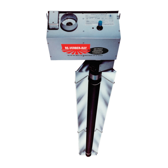
The AG2 Series Infra-Red Tube Heater is a positive pressure, two-stage radiant heater system. This insert
manual is a supplement to the Tube Heater General Manual and provides specific information related to
the AG2 Series model. All persons involved with the installation, operation and maintenance of the heater
system must read and understand the information in this insert manual and the accompanying Tube
Heater General Manual.
Improper installation, adjustment, alteration, service or maintenance can cause
property damage, injury or death. Read the installation, operation and maintenance
instructions thoroughly before installing or servicing this equipment.
This heater must be installed and serviced by trained gas installation and service
personnel only. Failure to comply could result in personal injury, asphyxiation, death,
fire or property damage.
In locations used for the storage of combustible materials, signs must be posted to
specify the maximum permissible stacking height to maintain the required clearances
from the heater to the combustibles. Signs must either be posted adjacent to the
heater thermostats or in the absence of such thermostats, in a conspicuous location.
Not for residential use! Do not use this heater in the home, sleeping quarters,
attached garages, etc. Installation of a commercial tube heater system in residential
indoor spaces may result in property damage, serious injury, asphyxiation or death.
For Your Safety
If you smell gas:
• Do not try to light any appliance.
• Do not touch any electrical switch.
• Do not use any phone in your building. • If you cannot reach your gas supplier, call the fire department.
!
!
WARNING
• Immediately call your gas supplier from a neighbor's phone.
• Follow the gas supplier's instructions.
Keep these instructions for future reference.
F/N: LIOAG2a-3M-5/07 (MWG)
Replaces F/N: LIOAG2-2M-2/06
Advertisement
Table of Contents

Related Manuals for Detroit Radiant Products AG2 Series


Summary of Contents for Detroit Radiant Products AG2 Series
- Page 1 For complete installation instructions, see the Tube Heater General Manual that accompanies this Series Insert Manual. The AG2 Series Infra-Red Tube Heater is a positive pressure, two-stage radiant heater system. This insert manual is a supplement to the Tube Heater General Manual and provides specific information related to the AG2 Series model.
-
Page 2: Table Of Contents
Series Contents .0 Safety..............3 Safety Labels and Locations . -
Page 3: Safety
125,000 / 95,000 AG2 - 40 - 125N NAT GAS For Stainless Steel Upgrades the Combustion Table is upgraded to 409 Stainless Steel DETROIT RADIANT PRODUCTS CO. Serial No. 0603DETR12345 0001 21400 HOOVER ROAD - WARREN, MI 48089 (586) 756-0950 www.reverberray.com... -
Page 4: Clearance To Combustibles
Series Safety • Safety Labels and Locations • Clearance to Combustibles F/N: LLTB007(2) CAUTION LED CODE FAULT STATUS FAULT CODE DELAY Initial flash on power up, Provide 24 Normal operation Immediate then steady off Volts Only Steady on Module failure / Internal fault Immediate This heater has a 24 Volt 1 flash Ignition failure 30-32 minutes control system. Do not connect 120 Volt power 2 or 3 flashes APS - Note: fan / intake / exhaust... - Page 5 Series Safety • Clearance to Combustibles Clearance to Combustibles WARNING Placement of explosive objects, flammable objects, liquids and vapors close to the heater may result in explosion, fire, property damage, serious injury or death. Do not store or use explosive objects, liquids or vapor in the vicinity of the heater. Clearance to combustibles is defined as the minimum distance that must exist between the tube surface, or reflector, and any combustible items (see Figure 1.1).
-
Page 6: Installation
Series Installation • Electrical Requirements Installation WARNING Improper installation, adjustment, alteration, service or maintenance can cause property damage, serious injury or death. Read and understand, the installation, operating and maintenance instructions thoroughly before installing or servicing this equipment. Only trained, qualified gas installation and service personnel may install or service this equipment. Not for residential use! Do not use this heater in the home, sleeping quarters, attached garages, etc. -
Page 7: Electrical Requirements
• Starting current 4.8 amps • Running current 1.1 amps The AG2 Series is equipped standard with an internal relay board. 24 volts must be supplied to each heater’s yellow control cord. 120 volts is supplied to the heater’s black cord; observe polarity. - Page 8 Series Installation • Wiring Before field wiring this appliance - Check existing wiring; replace if necessary. Note: If any of the original wire as supplied with the appliance must be replaced, it must be replaced with wiring material having a temperature rating of at least 105° C. Figure 2.3 •...
- Page 9 Series Installation • Wiring Figure 2.4 • Sample Brooder Installation Diagrams A. Center House Installation NOTE: Utilize elongated hangers (TP-19E) on houses 60 feet or more with center house mounting to allow for a wider throw pattern. B. Side Wall Installation NOTE: Mount Reflector at a 45°...
-
Page 10: Specifications
Series Installation • Product Specifications Specifications Chart 2.1 • Specifications AG2-20-65 N or LP 65,000 50,000 21’-7” 13’-0” 6’ to 9’ Alum 20.2 AG2-20-75 N or LP 75,000 50,000 21’-7” 13’-0” 7’ to 10’ Alum 20.2 AG2-30-65 N or LP 65,000 50,000 31’-3”... -
Page 11: Tube Installation Sequence
Series Installation • Tube Sequence • Heater Length Tube Installation Sequence Figure 2.5 • Tube Installation Sequence Important! The combustion chamber & radiant tube sections must be installed in the following order. 20 Foot 30 Foot 40 Foot Uncoated Aluminized Steel Secondary Combustion Chamber Location (150,000 BTU/H models only) 50 Foot... -
Page 12: Operation
Note: Different thermostats operate according to their particular features. Refer to thermostat specifications for details. AG2 Series heaters require a 24V, two-stage thermostat to operate. The burner control box is equipped with a 36” yellow 24V control wire. Do not supply 120V to the 24V connection. -
Page 13: Diagnostics
Series Operation • Diagnostics Diagnostics Lockout: The controls will automatically lockout the heater system when an external or system fault occurs. There are two types of lockout: Soft Lockout: The heater will attempt to light three times. In the event of a failed attempt to light, (gas pressure, valve, no flame sense etc.), the heater will enter a soft lockout period for 30 minutes and then attempt to light three more times before entering Hard Lockout mode. -
Page 14: Troubleshooting Guide
Series Troubleshooting Guide Troubleshooting Guide Turn up thermostat Check the power across the green Does the fan Is the power at and white wires of the yellow control blower turn on? the heater 120V? cord. Is there 24V power? Find the source Is the power across the 24V terminal and of the electrical the ground on the circuit board 24V? - Page 15 Series Troubleshooting Guide Bypassing any switch is intended for testing purposes only. Do not leave switch bypassed NOTICE during normal operation or the heater’s built-in safety mechanisms will be compromised. Process Start Corrective Is there 120V on the primary side Question Question Action...
- Page 16 Series Troubleshooting Guide Continued from page 14. The circuit board After the ignitor is warmed up, Test for 24V at gas valve and/or wiring does the gas valve open? during opening period (30-45 harness is faulty seconds after power to the and should be heater).
- Page 17 Series Troubleshooting Guide Bypassing any switch is intended for testing purposes only. Do not leave switch bypassed NOTICE during normal operation or the heater’s built-in safety mechanisms will be compromised. If the heater does not enter High Fire mode, check the following: Measure the voltage across Check the power across the green the red wire on the relay...
-
Page 18: Parts
Series Parts • Heater Components and Parts List Parts Figure 5.1 • Burner Assembly Components 264B, E, D 1402 383A 222A 200A or 201B 83, 83A TP-840A, 841A 303A 208A Chart 5.1 • Parts List Part No. Description Part No. Description TP-1 Control Box Cover TP-31B... - Page 19 Series Parts • Heater Components and Parts List Figure 5.2 • Tube & Reflector Components 20C, 20D 65 I 26F, 26G Part No. Description Part No. Description TP-200A Burner (65-100 MBH Models) TP-303A End Panel, Right TP-201B Burner (125-150 MBH Models) TP-304 Burner Control Box Outer Shell TP-204...
-
Page 20: Kit Contents Check List
• Kit Contents Check List Kit Contents Check List Chart 5.2 • Kit Contents for AG2 Series - Reference the length column for your model. AG2 Series Kit Contents TP-19B 4” Hanger with TP-19E Optional 4” TP-33B 1/2” Shut-Off Valve...
Need help?
Do you have a question about the AG2 Series and is the answer not in the manual?
Questions and answers