Table of Contents
Advertisement
Quick Links
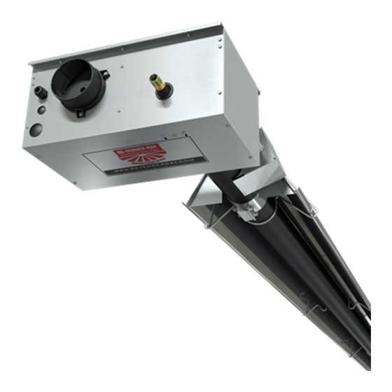
DX2 Series
Insert Manual
For complete installation instructions, reference the Tube Heater General Manual that
accompanies this insert manual.
The DX2 Series Infrared Tube Heater is a positive pressure, single-stage radiant heater system. This
insert manual is a supplement to the Tube Heater General Manual and provides specific information
related to the DX2 Series model. All persons involved with the installation, operation and maintenance of
the heater system must read and understand the information in this insert manual and the accompanying
Tube Heater General Manual.
Improper installation, adjustment, alteration, service or maintenance can cause
property damage, injury or death. Read the installation, operation and maintenance
instructions thoroughly before installing or servicing this equipment.
This heater must be installed and serviced by trained gas installation and service
personnel only. Failure to comply could result in personal injury, asphyxiation, death,
fire or property damage.
In locations used for the storage of combustible materials, signs must be posted to
specify the maximum permissible stacking height to maintain the required clearances
from the heater to the combustibles. Signs must either be posted adjacent to the
heater thermostats or in the absence of such thermostats, in a conspicuous location.
Not for residential use! Do not use this heater in the home, sleeping quarters,
attached garages, etc. Installation of a commercial tube heater system in residential
indoor spaces may result in property damage, serious injury, asphyxiation or death.
For Your Safety
If you smell gas:
• Do not try to light any appliance.
• Do not touch any electrical switch.
• Do not use any phone in your building. • If you cannot reach your gas supplier, call the fire department.
INSTALLER: Present this manual to the end user.
Keep these instructions in a clean and dry place for future reference.
Model#: ___________________ Serial #: _________________________
WARNING
!
• Immediately call your gas supplier from a neighbor's phone.
• Follow the gas supplier's instructions.
(located on rating label)
LIODX2a-Rev. 18111
Print: 1M -08/16_r2-01/17 (CDS)
Replaces: LIODX2a-5c-07/15 (CDS)
Advertisement
Table of Contents

Related Manuals for Detroit Radiant Products DX2 Series


Summary of Contents for Detroit Radiant Products DX2 Series
- Page 1 Tube Heater General Manual and provides specific information related to the DX2 Series model. All persons involved with the installation, operation and maintenance of the heater system must read and understand the information in this insert manual and the accompanying Tube Heater General Manual.
-
Page 2: Table Of Contents
Series Contents .0 Safety ..............3 Safety Labels and Locations . -
Page 3: Safety
AMPS - Running Combustion Chamber 4” BC Aluminized Heater Type: For Stainless Steel Upgrades the Combustion Table is upgraded to 409 Stainless Steel DETROIT RADIANT PRODUCTS CO. Serial No. 0603DETR12345 0001 21400 HOOVER ROAD - WARREN, MI 48089 (586) 756-0950 www.reverberray.com... -
Page 4: Clearance To Combustibles
Series Safety • Safety Labels and Locations • Clearance to Combustibles F/N: LLV3EP6 Left Panel (Fan Compartment) Primary Combustion Radiant 16” Burner Tube Chamber Tube(s) SERVICE ACCESS PANEL IGNITER & FLAME SENSE COMPARTMENT 1. Turn off gas & electricity. 2. Remove cover by lifting top cover upward and outward. - Page 5 Series Safety • Clearance to Combustibles Chart 1.1 • Clearance to Combustibles in Inches (see Figure 1.1 for Mounting Angles) Side Mounting Angle* Front Behind Below Model Number DX2 (20, 30, 40) - 50, 60 [N, P] 0° 45° with 1 side shield 0°...
-
Page 6: Installation
Electrical Requirements NOTICE The DX2 Series comes standard requiring a 120VAC connection to the thermostat. An optional 24VAC internal relay (24VAO) may be factory installed if the heater is to be controlled via a 24VAC thermostat. A 40VA transformer is necessary when using the 24VAO option. -
Page 7: Wiring
Series Installation • Wiring Wiring WARNING Electric Shock Field wiring to the tube heater must be connected and grounded in accordance with national, state, provincial, local codes and to the guidelines in the Tube Heater General Manual and Series Insert Manual. In the United States refer to the most current revisions to the ANSI/ NFPA 70 Standard and in Canada refer to the most current revisions to the CSA C22.1 Part I Standard. - Page 8 Series Installation • Wiring Before field wiring this appliance - Check existing wiring; replace if necessary. Note: If any of the original wire supplied with the appliance must be replaced, it must be replaced with wiring material having a temperature rating of at least 105° C. Figure 2.2 •...
- Page 9 Series Installation • Wiring Figure 2.3 • Alternative Wiring Diagrams A. TP-351A Ladder Diagram - Internal Relay Option (24VAO) Relay 120VAC Blower Indicator Lights 24VAC Gas Valve Thermostat Terminal Pressure Switch Igniter IGNITION MODULE B. TP-351A Block Diagram - Internal Relay Option (24VAO) Burner Terminal Block Relay...
-
Page 10: Specifications
Series Installation • Product Specifications Specifications Chart 2.1 • Specifications DX2-20-50 N or P 50,000 21’-8” 13’-0” 9’ to 15’ Alum Alum 20.2 DX2-20-60 N or P 60,000 21’-8” 13’-0” 10’ to 15’ Alum Alum 20.2 DX2-20-75 N or P 75,000 21’-8”... -
Page 11: Tube Installation Sequence
Series Installation • Tube Sequence • Heater Length Tube Installation Sequence Figure 2.4 • Tube Installation Sequence Important! The combustion chamber & radiant tube sections must be installed in the following order. 20 Foot 30 Foot 40 Foot Stainless Steel Clamp on 175 MBH models (P/N: TP-220). 50 Foot Stainless Steel Clamp on 175 - 200 MBH models (P/N: TP-220). -
Page 12: Operation
NOTE: Different thermostats operate according to their particular features. Refer to thermostat specifications for details. The DX2 Series comes standard requiring a 120VAC connection to the thermostat. An optional 24VAC internal relay (24VAO) may be factory installed if the heater is to be controlled via a 24VAC thermostat. -
Page 13: Operational Indicator Lights
Series Operation • Diagnostics Operational Indicator Lights The externally located operational indicator lights are provided to assist in troubleshooting of the heater. Refer to the following pages for additional troubleshooting. Figure 3.1 • Operational Indicator Lights PRESSURE VALVE SWITCH Light 1 Light 2 Indicates Valve Indicates Pressure... -
Page 14: Troubleshooting Guide
Series Troubleshooting Guide Troubleshooting Guide Turn up thermostat Is the power at the Does the fan Is the blower heater 120V? blower turn on? obstructed? Find the source of the electrical Remove obstruction problem between panel and heater. and lubricate fan. Is the inlet or the outlet of the unit obstructed (i.e., Does the switch... - Page 15 Series Troubleshooting Guide NOTICE Bypassing any switch is intended for testing purposes only. Do not leave switch bypassed during normal operation or the heater’s built-in safety mechanisms will be compromised. Start Process Corrective Is 120V coming Correct Question Question Action to the fan? wiring.
- Page 16 Series Troubleshooting Guide Continued from page 14 After igniter is Test for 120V at valve opening period (usually 30 to 45 seconds warmed up, does after power to heater). Is there 120V to valve for 8 seconds? gas valve open? Replace circuit board and/or wiring harness.
- Page 17 Series Troubleshooting Guide Check to make sure gas pressure is within minimum and maximum inputs, as indicated on burner rating plate. Replace gas valve. Is gas pressure OK? Correct problem. Confirm manifold pressure is Were the gas lines purged of air? correct and/or gas orifice is not plugged and is the correct size.
-
Page 18: Parts
Series Parts • Heater Components and Parts List Parts Figure 5.1 • Burner Assembly Components NOPS 302, 302A 383A 304, 804 351A 352A 222A 380, 202 200A or 201B TP-240, 241 208B Chart 5.1 • Parts List Part No. Description Part No. - Page 19 Series Parts • Heater Components and Parts List Figure 5.2 • Tube & Reflector Components 20C, 20D 26A, 26D 21B, 220 26A, 26B, 26E Part No. Description Part No. Description TP-202 16” Burner Tube with Flange (fittings included) TP-301 Center Divider Panel TP-204 Gas Orifice (consult factory) TP-302...
-
Page 20: Kit Contents Check List
Kit Contents Check List Series Kit Contents Check List Chart 5.2 • Kit Contents for DX2 Series - Reference the length column for your model. DX2 Series Kit Contents TP-19B 4” Hanger with TP-82 4” Reflector TP-33B 1/2” Shut-Off Valve...
Need help?
Do you have a question about the DX2 Series and is the answer not in the manual?
Questions and answers