Table of Contents
Advertisement
Quick Links
SV Series
Insert Manual
For complete installation instructions, see the Tube Heater General Manual
that accompanies this Series Insert Manual.
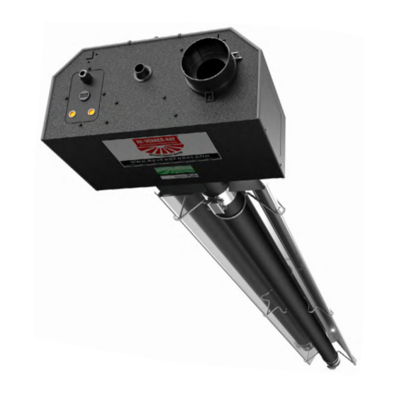
The SV Series Infrared Tube Heater is a negative pressure, single-stage radiant heater system. This insert
manual is a supplement to the Tube Heater General Manual and provides specific information related to
the SV Series model. All persons involved with the installation, operation and maintenance of the heater
system must read and understand the information in this insert manual and the accompanying Tube
Heater General Manual.
Improper installation, adjustment, alteration, service or maintenance can cause
property damage, injury or death. Read the installation, operation and maintenance
instructions thoroughly before installing or servicing this equipment.
This heater must be installed and serviced by trained gas installation and service
personnel only. Failure to comply could result in personal injury, asphyxiation, death,
fire or property damage.
In locations used for the storage of combustible materials, signs must be posted to
specify the maximum permissible stacking height to maintain the required clearances
from the heater to the combustibles. Signs must either be posted adjacent to the
heater thermostats or in the absence of such thermostats, in a conspicuous location.
Not for residential use! Do not use this heater in the home, sleeping quarters,
attached garages, etc. Installation of a commercial tube heater system in residential
indoor spaces may result in property damage, serious injury, asphyxiation or death.
For Your Safety
If you smell gas:
• Do not try to light any appliance.
• Do not touch any electrical switch.
• Do not use any phone in your building. • If you cannot reach your gas supplier, call the fire department.
WARNING
!
• Immediately call your gas supplier from a neighbor's phone.
• Follow the gas supplier's instructions.
Keep these instructions for future reference.
LIOSVa-Rev. 18111
Print: 1M-9/12_r1-2/13 (CDS)
Replaces: LIOSVa-1M-1/11 (DRP)
Advertisement
Table of Contents

Related Manuals for Detroit Radiant Products SV Series


Summary of Contents for Detroit Radiant Products SV Series
- Page 1 For complete installation instructions, see the Tube Heater General Manual that accompanies this Series Insert Manual. The SV Series Infrared Tube Heater is a negative pressure, single-stage radiant heater system. This insert manual is a supplement to the Tube Heater General Manual and provides specific information related to the SV Series model.
-
Page 2: Table Of Contents
Series Contents .0 Safety..............3 Safety Labels and Locations . -
Page 3: Safety
W.C.P. DEGREES Combustion Chamber: 4” Black Coated Aluminized DESIGN COMPLIES WITH: ANSI Z83.20b-2004-GAS FIRED LOW INTENSITY INFRA-RED HTR. DETROIT RADIANT PRODUCTS COMPANY Serial No.: 0807XXXXXXXXXX 0001 21400 HOOVER ROAD - WARREN, MI (586) 756-0950 www.drp-co.com Rating Plate F/N: LLTB018 (Natural Gas) -
Page 4: Clearance To Combustibles
Series Safety • Safety Labels and Locations • Clearance to Combustibles PRESSURE VALVE SWITCH F/N: LLV3EP6 Left Panel Combustion Radiant 16” Burner Tube Chamber Tube SERVICE ACCESS PANEL IGNITER & FLAME SENSE COMPARTMENT 1. Turn off gas & electricity. 2. Remove cover by lifting top cover upward and outward. - Page 5 Series Safety • Clearance to Combustibles Chart 1.1 • Clearance to Combustibles in Inches (see Figure 1.1 for Mounting Angles) Side Mounting Angle* Front Behind Below Model Number SV (20, 30, 40) - 50, 60 [N, P] 0° 45° with 1 side shield 0°...
-
Page 6: Installation
Series Installation • Gas Requirements • Electrical Requirements Installation WARNING Not for residential use! Improper installation, adjustment, alteration, service or maintenance can cause property damage, serious injury or death. Read and understand, the installation, operating and maintenance instructions thoroughly before installing or servicing this equipment. Only trained, qualified gas installation and service personnel may install or service this equipment. -
Page 7: Thermostat
The span of wire must allow for several inches of heater expansion. Thermostat SV Series heaters require a 120VAC thermostat to operate. NOTE: Different thermostats operate according to their particular features. Refer to thermostat specifications for details. - Page 8 18 inches from the reflector and outside of the clearance to combustibles zone. 1/4” female spade terminals (as supplied). SV Series Power Box Burner Box Assembly 1/4” female spade terminals (as supplied). Up to four...
- Page 9 Series Installation • Wiring Figure 2.2 • Internal Wiring Diagrams A. TP-1251 Ladder Diagram L1 120V Blower Exhauster Power Box Assembly 120V Fuse 24V Indicator Light Switch Light ON = Control Fault Flame 2 Flashes = Flame, No Call for Heat 3 Flashes = Ignition Lockout Ignition Module S1 L1 L2 S2...
-
Page 10: Specifications
Series Installation • Specifications Specifications Chart 2.1 • Specifications SV-20-50 N or LP 50,000 22’-7” 13’-0” 9’ to 14’ Alum Alum 20.2 SV-20-60 N or LP 60,000 22’-7” 13’-0” 10’ to 15’ Alum Alum 20.2 SV-20-75 N or LP 75,000 22’-7”... -
Page 11: Tube Installation Sequence
Series Installation • Tube Installation Sequence • Heater Length Tube Installation Sequence Figure 2.4 • Tube Installation Sequence Important! The combustion chamber & radiant tube sections must be installed in the following order. 20 Foot 30 Foot 40 Foot 50 Foot Stainless steel clamp location on 175 - 200 MBH models only (P/N: TP-220). -
Page 12: Exhauster Mounting Details
Series SV Series Installation • Exhauster Mounting Details Exhauster Mounting Details When installing this heater in a U-shaped configuration, the exhauster assembly and the burner control box must not interfere with each other. When looking at the U-shaped configuration from behind, the burner control box is on the left and the exhauster assembly is on the right. -
Page 13: Operation
Series Operation • Sequence of Operation • Operational Indicator Lights Operation WARNING This heater must be installed and serviced by trained gas installation and service personnel only. Do not bypass any safety features or the heater’s built in safety mechanisms will be compromised. -
Page 14: Troubleshooting Guide
Series Troubleshooting Guide Troubleshooting Guide Turn up thermostat Is the power at the Does the exhauster Is the exhauster exhauster 120V? fan turn on? obstructed? Find the source of the Remove obstruction electrical problem. and lubricate fan. Is the inlet or the outlet of the unit obstructed (i.e., Does the pressure Is the light burnt out? - Page 15 Series Troubleshooting Guide Bypassing any switch is intended for testing purposes only. Do not leave switch bypassed NOTICE during normal operation or the heater’s built-in safety mechanisms will be compromised. Start Corrective Process The fan is faulty Question Action Question and must be replaced.
- Page 16 Series Troubleshooting Guide Continued from page 14 Is the proper gauge wire used between Is the gas supply Does the the exhauster power box assembly and to the heater in burner ignite? the burner control box? the ON position? Turn on. Use 14 gauge multistrand wire.
- Page 17 Series Troubleshooting Guide Use larger gauge wire. Correct pressures. Check voltage at burner Check to make sure gas pressure is within Were the gas control box during igniter minimum and maximum inputs, as indicated on lines purged of warm up. Is it at least 24V? burner rating plate.
-
Page 18: Parts
Series Parts • Heater Components and Parts List Parts Figure 5.1 • Burner Assembly Components 1202 1251 1283 222, 222A 1280 1250 804, 1204 200A, 201B 1240A, 1241A 208A Chart 5.1 • Parts List Part No. Description Part No. Description TP-1 Control Box Cover TP-65I... - Page 19 Series Parts • Heater Components and Parts List Figure 5.2 • Tube & Reflector Components THCS 1215 1243 1526A 20C/D* 1266 1289 1232 1220 1229 1297 26A/D* 1255 21B, 220 26A/B/E* Part No. Description Part No. Description TP-219 Differential Vinyl Sensing Tube TP-1250 24V Mini Igniter (burner)
-
Page 20: Kit Contents Check List
Parts • Kit Contents Check List • Approvals • Limited Warranty Kit Contents Check List Chart 5.2 • Kit Contents for SV Series - Reference the length column for your model. SV Series Kit Contents TP-19B 4” Hanger with TP-82 4” Reflector TP-33B 1/2”...
Need help?
Do you have a question about the SV Series and is the answer not in the manual?
Questions and answers