Table of Contents
Advertisement
Quick Links
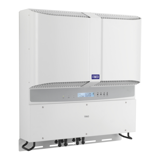
Solar Inverter
PVI-10.0/12.5-TL-OUTD
Quick Installation Guide
In addition to what is explained in this quick installation guide, the safety and installation information provided in the product manual must be read and
followed. The technical documentation for the product is available at the website.
The device must be used in the manner described in the manual. If this is not the case the safety devices guaranteed by the inverter might be
ineffective.
Advertisement
Table of Contents

Related Manuals for Fimer PVI-10.0-TL-OUTD


Summary of Contents for Fimer PVI-10.0-TL-OUTD
- Page 1 Solar Inverter PVI-10.0/12.5-TL-OUTD Quick Installation Guide In addition to what is explained in this quick installation guide, the safety and installation information provided in the product manual must be read and followed. The technical documentation for the product is available at the website. The device must be used in the manner described in the manual.
-
Page 2: Labels And Symbols
Inverter serial number Week/Year of manufacture Main technical data Fimer S.p.A. Via Tortona, 25 - I 20144 Milano (MI) The labels attached to the equipment must NOT be removed, damaged, dirtied, hidden,etc... If the service password is requested, the field to be used is the serial number -SN: YYWWSSSSSS-... -
Page 3: Lifting And Transport
Reduction in the dielectric resistance of the air that, in the presence of high operating voltages (DC input), can create electric arcs (discharges) that can reach the point of damaging the inverter All installations at altitudes of over 2000 metres must be assessed case by case with the FIMER Service department. Installation position... -
Page 4: Assembly Instruction
6. Assembly Instruction Wall mounting -During installation, do not place the inverter with its front facing towards the ground. -Position the bracket (01) so that it is perfectly level on the wall and use it as a boring template. -Drill the 3 holes required using a drill with 10mm bit. The holes must be about 70mm deep. -
Page 5: Line Cable And Protection Devices
300 mA FIMER declares that the FIMER transformerless inverters, in terms of their construction, do not inject continuous ground fault currents and therefore there is no requirement that the differential protection installed downstream of the inverter be type B in accordance with IEC 60755 / A 2. - Page 6 Warning! After the grid standard was set you have 24 hours to make any changes to the grid standard value; 24 hours later the “Country Select.” functionality will be blocked, and any subsequent changes can only be made using a password provided on request by FIMER After you have set the “Country”...
- Page 7 14. Structure of the display menu FIMER inverters are equipped with a Display (05), consisting of 2 lines of 16 characters each, which can be used to: -Display the operating state of the inverter and the statistical data -Display the service messages for the operator...
-
Page 8: Input Protection
With regard to purchase orders, the agreed particulars reproduction, disclosure to third parties or utilization of representative or visit: shall prevail. FIMER does not accept any responsibility its contents – in whole or in parts – is forbidden without whatsoever for potential errors or possible lack of prior written consent of FIMER.