baltur BGN 200 LX Instruction
Hide thumbs
Also See for BGN 200 LX:
- Maintenance, use and installation manual (53 pages) ,
- Instruction manual (133 pages) ,
- Startup manual (50 pages)
Table of Contents

Subscribe to Our Youtube Channel
Related Manuals for baltur BGN 200 LX


Summary of Contents for baltur BGN 200 LX
- Page 1 IT - GB - SP - FR - Istruzioni per bruciatori modello BGN 200 LX / LX-V - Instruction for burners model BGN 300 LX / LX-V - Instrucciónes para quemadores modelos - Mode d’emploi bruleûr BGN 390 LX / LX-V...
- Page 2 IT - Prima di iniziare a usare il bruciatore leggere attentamente quanto esposto nell’ouscolo “AVVERTENZE PER L’UTENTE, PER L’USO IN SICUREZZA DEL BRUCIATORE” presente a corredo del manuale istruzioni, che costituisce parte integrante ed essenziale del prodotto. - Leggere attentamente le istruzioni prima di mettere in funzione il bruciatore o di eseguire la manutenzione.
- Page 3 ITALIANO PAGINA Avvertenze per l’utente per l’uso in sicurezza del bruciatore ................“ Caratteristiche tecniche ............................“ Linea di alimentazione gas - Fissaggio del bruciatore alla caldaia ..............“ Rilevazione pressione in camera di combustione ....................“ Collegamenti elettrici - Descrizione del funzionamento - Descrizione del funzionamento della modulazione ... “ Accensione e regolazione a gas ........................
-
Page 4: Dichiarazione Di Conformità
Dichiarazione di Conformità Statement of Conformity Dichiariamo, sotto la Nostra responsabilità, che i hereby declare under Nostri prodotti contrassegnati “CE” Serie: responsibility, that our “CE” marked products Se- Sparkgas…; BTG…; BGN…; Minicomist…; ries: Comist…; RiNOx…, BT…; BTL…; GI…; GI… Sparkgas…; BTG…; BGN…; Minicomist…; Mist;... -
Page 5: Declaración De Conformidad
Declaración de Conformidad Déclaration de conformité Declaramos bajo nuestra responsabilidad que Nous déclarons, sous notre responsabilité, que nos produits portant la marque “CE” nuestros productos identificados con el marcado “CE” Serie: Séries : Sparkgas…; BTG…; BGN…; Minicomist…; Co- Sparkgas…; BTG…; BGN…; mist…;... -
Page 6: Avvertenze Per L'utente Per L'uso In Sicurezza Del Bruciatore
Rivolgersi esclusivamente a personale professionalmente qualificato. L’eventuale riparazione dei prodotti dovrà essere effettuata solamente da un centro di assistenza autorizzato dalla BALTUR utilizzando esclusivamente ricambi originali. Il mancato rispetto di quanto sopra, può compromettere la sicurezza dell’apparecchio. Per garantire l’efficienza dell’ apparecchio e per il suo corretto funzionamento é indispensabile fare effettuare da personale professionalmente qualificato la manutenzione periodica attenendosi alle indicazioni fornite dal costruttore. - Page 7 AVVERTENZE PER L’UTENTE PER L’USO IN SICUREZZA DEL BRUCIATORE ALIMENTAZIONE ELETTRICA • La sicurezza elettrica dell’apparecchio è raggiunta soltanto quando lo stesso è corretamente collegato a un’efficace impianto di messa a terra, eseguito come previsto dalle vigenti norme di sicurezza. E’ necessario verificare questo fondamentale requisito di sicurezza. In caso di dubbio, richiedere un controllo accurato dell’impianto elettrico da parte di personale professionalmente qualificato, poiché...
-
Page 8: Warning Notes For The User How To Use The Burner Safely
In such case get in touch with only qualified technicians. Any product repairs must only be carried out by BALTUR authorised assistance centres using only original spare parts. Failure to act as above may jeopardise the safety of the equipment. -
Page 9: Electrical Supply
WARNING NOTES FOR THE USER HOW TO USE THE BURNER SAFELY ELECTRICAL SUPPLY • The equipment is electrically safe only when it is correctly connected to an efficient ground connection carried out in accordance with current safety regulations. It is necessary to check this essential safety requirement. If in doubt, call for a careful electrical check by a qualified technicians, since the manufacturer will not be liable for any damage caused by a poor ground connection. - Page 10 Diríjase exclusivamente a personal cualificado profesionalmente. La eventual reparación de los aparatos tiene que hacerla solamente un centro de asistencia autorizado por BALTUR utilizando exclusivamente repuestos originales. Si no se respeta lo anteriormente se puede comprometer la seguridad del aparato. Para garantizar la eficacia del aparato y para que funcione correctamente es indispensable que el personal cualificado profesionalmente realice el mantenimiento periódicamente ateniéndose a las indicaciones...
- Page 11 ADVERTENCIAS DIRIGIDAS AL USUARIO PARA USAR EL QUEMADOR EN CONDICIONES DE SEGURIDAD PRELIMINARES ALIMENTACIÓN ELÉCTRICA • La seguridad eléctrica del aparato se consigue solo cuando el mismo está conectado correctamente a una buena instalación de puesta a tierra, realizado tal y como establecen las normas de seguridad vigentes. Es necesario comprobar este requisito de seguridad funda- mental.
- Page 12 S’adresser exclusivement à du personnel professionnellement qualifié. L’éventuelle réparation des produits doit être effectuée par un centre de service après-vente agréé par BALTUR en utilisant exclusivement des pièces détachées d’origine. Le non-respect de cette recommandation peut compromettre la sécurité de l’appareil. Pour garantir l’efficience de ce dernier et pour que son fonctionnement soit correct, il est indispensable de faire effectuer l’entretien périodique par du personnel professionnellement qualifié...
-
Page 13: Alimentation Electrique
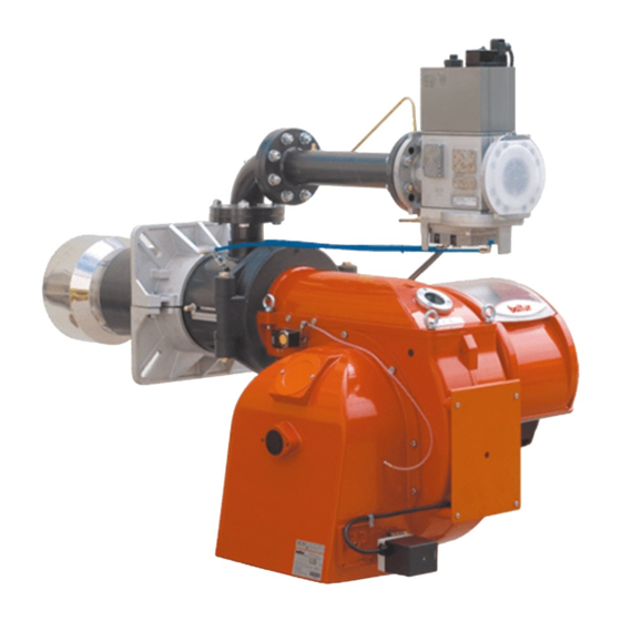
RECOMMANDATIONS A L’ATTENTION DE L’UTILISATEUR POUR UN USAGE DU BRULEUR EN TOUTE SECURITE INTRODUCTION ALIMENTATION ELECTRIQUE • La sécurité électrique de l’appareil est atteinte uniquement lorsque ce dernier est correctement raccordé à une installa- tion de mise à la terre efficace, exécutée comme prévu par les normes de sécurité en vigueur. Cette condition requise de sécurité... - Page 14 CARATTERISTICHE TECNICHE / TECHNICAL DATA / CARACTERISTIQUES TECHNIQUES / CARACTERISTICAS TECNICAS 200 LX 300 LX 390 LX 540 LX 2150 3600 3950 5900 POTENZA TERMICA / THERMIC CAPACITY / PUISSANCE THERMIQUE / POTENCIA TERMICA MOTORE / MOTOR / MOTEUR / MOTOR 2870 2870 2870...
-
Page 15: Gas Supply Line
GAS SUPPLY LINE The general gas supply situation is 2) For the better working of the GENERAL DIAGRAM FOR illustrated here alongside The gas pressure regulator it is advisable INSTALLATION OF GATE-FILTER- train is EN 676 certified and is sup- to attach it to horizontal piping STABILIZER-ANTI-VIBRATION JOINT-OPENABLE PITTING... -
Page 16: Application Of The Burner To Boiler
APPLICATION OF THE BURNER TO BOILER COMBUSTION HEAD ASSEMBLY Following the drawing, connect the tube on the attachment on the flan- ge and fix with the screw To put in place insulation flange 2, which must be positioned between the burner and the plate of boiler 1, the end of the combustion head must first be removed. - Page 17 Ø 12 in order to install the pressure take-up hose (supplied with the burners), whose position is shown in the flange drilling-plate drawnings n° 0002471100 - 0002933821. N° 0002934900 FOR MODELS BGN 200 LX ÷ BGN 390 LX Rev.20/07/20026 Rigid pipe that reads combustion...
-
Page 18: Electrical Connections
5) to properly resecure ELECTRICAL CONNECTIONS transparent door on the panel proceed as indicated in The three-phase power supply line position the hooks at their must have a switch with fuses. hooking points and (9) slide the The regulations further require door in the direction indicated by a switch on the burner’s power the arrow until it clicks. - Page 19 DESCRIPTION OF WORKING Closing switch 1, if the thermostats are closed, the voltage reaches the com- mand and control equipment (switching on of LED 2) which starts it working. The fan motor is thus switched on (LED 3) to carry out the preventilation of the combustion chamber, at the same time the air damper control servo motor mo- ves to the opening position correspon-...
- Page 20 6) Apply a pressure gauge with IGNITION AND GAS suitable scale to the gas pres- REGULATION (METHANE) sure take-off to measure the regulation value (if the expected 1) Make sure that the combus- pressure rate allows it, it is pref- tion head penetrates into erable to use a water column the combustion chamber by...
- Page 21 in the combustion head. Remedy flow rate automatically adjust The pressure switch must thus is by operating on the combus- to the air supply. Then, oper- be set to start by closing the tion head regulation device, by contact (a normally open contact) ate on the cam regulating the when air pressure in the burner adjusting the closing or opening...
- Page 22 cally connected in series; thus, the specific control box. Said operating at the maximum desired value is shown in the wiring the start (intended as circuit output. In practice, the regulation opening) of any one of the gas diagram. It may be necessary must start with the device that closes pressure switches does not to experimentally search the...
-
Page 23: Maintenance
the mouth. MAINTENANCE Be careful when assembling again, so as to prevent the electrodes from The burner does not need special to earth or in short circuit. maintenance. However, it is advis- Also check that the ignition electrode able to check that the gas filter is spark only occurs between the same clean. -
Page 24: Combustion Head Adjustment Diagram
field. BGN 200 ÷ 390 LX / LX-V N° 0002934430 ELECTRODES ADJUSTMENT DIAGRAM Rev. 23/09/2004 Ionisation electrode MOD. Ignition electrode BGN 200 LX/LX-V Flame disk BGN 300 LX/LX-V Gas diffuser BGN 390 LX/LX-V Gas delivery pipe 51 / 119 0006081062_200709... - Page 25 N° 0002933850 BGN 540 LX / LX-V ELECTRODES ADJUSTMENT DIAGRAM Rev. 12/06/2002 CONTROL BOX FOR LFL 1... SERIES 02 GAS BURNERS - The flame detector test and false Control box for burners of ave- As regards the burner control flame test start immediately after rage and high power, with forced - The equipment allows operation the tolerated post-combustion...
- Page 26 Electrical connections The burner manufacturer’s diagram is valid for the relief valve connections. Flame signal amplifier LEGEND Fault indicator light Ready for operation indicator Thermostat or safety pressure For the entire catalogue sheet switch Air damper Limit switch commutation In the case of servomotor: Air pressure switch contact for air damper OPEN limit switch commutation con-...
- Page 27 Notes on the programmer Programmer sequence Output signals on terminal 54 / 119 0006081062_200709...
- Page 28 27 t20 Time up to automatic closu- Times Legend Safety standards time (50 Hz) in seconds re of programmer mechani- • In association with the use of sm after burner start-up QRA…, earthing of terminal 31.5 t1 Pre-ventilation time with 22 is compulsory.
- Page 29 ▌ Lock-out stop, due to lack Control program in the event of Lock-out stop, because of lack of air pressure signal. of flame signal during burner stopping, indicating position of stop Any lack of pressure from operation. As a rule, in the event of any kind this moment onwards will of stop, the fuel flow is cut off im- If a lock-out stop occurs at any...
- Page 30 TWO-STAGE GAS BURNERS: TROUBLE-SHOOTING GUIDE DETAILS OF PROBLEM POSSIBLE CAUSE SOLUTION 1) Disturbance to ionization current 1) Invert the ignition transformer The apparatus goes into “lock- power supply (230V side) and out” with the flame (red light from ignition transformer. check using an analog micro- on).
- Page 31 - ISTRUZIONI VALVOLA MONOBLOCCO CON FUNZIONAMENTO A MODULAZIONE CONTINUA - INSTRUCTIONS FOR MONOBLOC VALVE WITH CONTINUOUS MODULATION OPERATION N° 0002910621 - INSTRUCCIONES SOBRE LA VÁLVULA MONOBLOQUE CON FUNCIONAMIENTO CON Rev. 22/10/2004 MODULACIÓN CONTINUA - INSTRUCTIONS VANNE MONOBLOC AVEC FONCTIONNEMENT A MODULATION CONTINUE DUNGS mod.
- Page 32 Conexión eléctrica Puesta a tierra conforme a las normas locales Tomas de presión 1,3,4,6 Tapón con tornillo G 1/8 Toma para medir la presión Tapón con tornillo M4 7,8,9 Rosca interna G 1/8 para los tubos medición impulsos de presión P Tapa del filtro 95 / 119 0006081062_200709...
- Page 33 Instalación de los tubos de medición impulsos de presión : presión del gas en la entrada S10: 5-100 mbar S30: 100-360 mbar : presión en el soplador, aire 0,4 -100 mbar : presión en la caldera - 2 mbar … + 5 mbar o atmosférica : presión en el quemador, gas 0,5 -100 mbar 96 / 119...
- Page 34 DUNGS mod. DMV-VEF 5065/11 - 5125/11 ISTRUZIONI VALVOLA ELETTROMAGNETICA DOPPIA CON FUNZIONAMENTO A MODULAZIONE CONTINUA INSTRUCTIONS FOR DOUBLE SOLENOID VALVE gAS-AIR-RATIO CONTROL INSTRUCTIONS ELECTROVANNE DOUBLE RÉGLAGE COMBINÉ DU GAZ ET DE L’AIR N° 0006080717 Rev. 2002/06 97 / 119 0006081062_200709...
- Page 35 98 / 119 0006081062_200709...
- Page 36 99 / 119 0006081062_200709...
- Page 37 Notice d'emploi et de mon- Gebruiks- en montage- Instrucciones de servicio Instruções de serviço e tage aanwijzing y de montaje montagem Electrovanne double Dubbele magneetafsluiter Válvula magnética doble Válvula electromagnética dupla Réglage combiné du gaz traploze werking de modo operativo conti- Controlo combinado de et de l'air Type DMV-VEF...
- Page 38 Prises de pression Drukmeetpunten Tomas de presión Tomadas de pressão DMV-VEF 5065/11 - 5125/11 min. 5 x DN p , extern PN1, DN 4 1, 6 2, 3, 4, 5 Bouchon G 1/8 Bouchon G 1/8 Raccordement des pressions p ademstop G 1/8 sluitschroef G 1/8 sluitschroef G 1/8...
- Page 39 Tableau récapitulatif / Overzicht / Visión sinóptica / Vista geral DMV-VEF 5065/11 - 5125/11 Notre fourniture ne comprend pas la tuyauterie de raccordement. Impulsleidingen maken geen onderdeel uit van de levering. Las líneas de impulsos no forman parte del volumen de suministro. As linhas de impulsos não fazem parte do fornecimento.
- Page 40 Instructions de montage des con- Montagevoorschrift Instrucciones de montaje de lí- Instruções de montagem duites d'impulsions impulsleidingen neas de impulso Linhas de impulsos Les conduites d'impulsions Impulsleidingen p , p en Las líneas de impulsos pL, As linhas de impulsos p et p doivent être en p moeten overeenkomen...
- Page 41 N° 0002910621 / 0006080717 DUNGS mod. MB-VEF BO1 / DMV-VEF Rev. 22/10/2004 Taratura del gruppo regolazione-pressione Setting the pressure – adjustment unit The pressure – adjustment unit is factory set. Il gruppo regolazione- pressione viene pre-tarato in fabbrica. I valori di taratura devono essere poi Settings should then be adapted on site to suit adattati sul posto alle esigenze dell‘...
- Page 42 N° 0002910621 / DUNGS mod. MB-VEF BO1 / DMV-VEF 0006080717 Rev. 22/10/2004 TARAGE DU GROUPE DE RÉGLAGE – PRESSION TARADO DEL GRUPO DE REGULACIÓN - PRESIÓN Le groupe de réglage – pression est préréglé en usine. En- El grupo de regulación - presión se tara previa- suite, les valeurs de tarage doivent être adaptées sur place mente en la fábrica.
- Page 43 N° 0002910621 / 0006080717 DUNGS mod. MB-VEF BO1 / DMV-VEF Rev. 22/10/2004 max/maxi = 100 mbar V max/maxi = 3:1 min./mini min./mini = 0,4 mbar V min./mini = 0,75:1 max/maxi Nullpunkorrektur ± 1 mbar max/maxi = 100 mbar Zero point adjustement ± 1 mbar Correction point zéro ±...
- Page 44 SCHEMA ELETTRICO / WIRING DIAGRAM / ELECTRIC DIAGRAM 107 / 119 0006081062_200709...
- Page 45 SCHEMA ELETTRICO / WIRING DIAGRAM / ELECTRIC DIAGRAM 108 / 119 0006081062_200709...
- Page 46 SCHEMA ELETTRICO / WIRING DIAGRAM / ELECTRIC DIAGRAM 109 / 119 0006081062_200709...
- Page 47 SCHEMA ELETTRICO / WIRING DIAGRAM / ELECTRIC DIAGRAM 110 / 119 0006081062_200709...
- Page 48 SCHEMA ELETTRICO / WIRING DIAGRAM / ELECTRIC DIAGRAM 111 / 119 0006081062_200709...
- Page 49 SCHEMA ELETTRICO / WIRING DIAGRAM / ELECTRIC DIAGRAM 112 / 119 0006081062_200709...
- Page 50 SCHEMA ELETTRICO / WIRING DIAGRAM / ELECTRIC DIAGRAM 113 / 119 0006081062_200709...
- Page 51 SCHEMA ELETTRICO / WIRING DIAGRAM / ELECTRIC DIAGRAM 114 / 119 0006081062_200709...
- Page 52 SCHEMA ELETTRICO / WIRING DIAGRAM / ELECTRIC DIAGRAM 115 / 119 0006081062_200709...
- Page 53 SCHEMA ELETTRICO / WIRING DIAGRAM / ELECTRIC DIAGRAM 116 / 119 0006081062_200709...
- Page 54 SCHEMA ELETTRICO / WIRING DIAGRAM / ELECTRIC DIAGRAM 117 / 119 0006081062_200709...
- Page 55 SCHEMA ELETTRICO / WIRING DIAGRAM / ELECTRIC DIAGRAM 118 / 119 0006081062_200709...
- Page 56 SCHEMA ELETTRICO / WIRING DIAGRAM / ELECTRIC DIAGRAM 119 / 119 0006081062_200709...
- Page 57 Il presente catalogo riveste carattere puramente indicativo. La casa, pertanto, si riserva ogni possibilità di modifica dei dati tecnici e quant’altro in esso riportato. Technical data in this brochure are given as information only. Baltur reserves the right to change specification, without notice.
Need help?
Do you have a question about the BGN 200 LX and is the answer not in the manual?
Questions and answers