
Related Manuals for baltur BGN 40 DSPGN


Summary of Contents for baltur BGN 40 DSPGN
- Page 1 - Instruction for burners model BGN 40 DSPGN BGN 200 DSPGN BGN 60 DSPGN BGN 250 DSPGN BGN 100 DSPGN BGN 300 DSPGN BGN 120 DSPGN BGN 350 DSPGN BGN 150 DSPGN 2005/12 Edition Cod. 0006080458...
- Page 2 Statement of Conformity We hereby declare under our own responsibility, that our “CE” marked products Series: Sparkgas…; BTG…; BGN…; Minicomist…; Comist…; RiNOx…, BT…; BTL…; GI…; GI…Mist; PYR…; TS… Description: domestic and industrial blown air burners fired by gas, oil and dual fuel respect the minimal regulation of the European Directives: •...
- Page 3 Technical data BURNERS N° 9441/2 BGN 40 DSPGN ÷ 350 DSPGN Rev. 05/07/01 BGN 40 BGN 60 BGN 100 BGN 120 BGN 150 DSPGN DSPGN DSPGN DSPGN DSPGN POTENZA TERMICA / THERMIC CAPACITY 1200 1428 MAX kW PUISSANCE THERMIQUE PORTATA (Gas naturale) MAX m³/h...
-
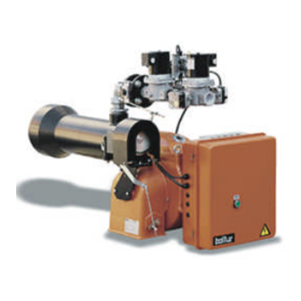
Page 4: Component List
N° 9441/1 COMPONENT LIST Rev. 07/11/95 Combustion head Gasket Burner mounting flange Butterfly valve Operating valve Safety valve Gas pressure switch max. Switch for the valve tightness control lock-out Head air control knob 10) Hinge 11) Air control servomotor 12) Electric control panel 13) Pilot operating valve 14) Motor 15) Pilot safety valve... - Page 5 N° 9441/1 Dimensions Rev. 07/11/95...
- Page 6 N° 7604-2 BGN 40 DSPGN ÷ 100 DSPGN Rev. 02/02/96 N° 7605-5 BGN 120 DSPGN ÷ 350 DSPGN Rev. 17/11/97...
- Page 7 N° 8917/1 DRAWING SHOWING THE GAS TRAIN ASSEBBLY Rev. BGN 40 - 60 - 100 - 120M - DSPGN with SQN 30 401 A 2700 modulating servomotor DRAWING SHOWING THE GAS TRAIN ASSEMBLY N° 8805 BGN 40 - 60 - 100 - 120 - 150 M - DSPGN Rev.
-
Page 8: Application Of The Burner To Boiler
APPLICATION OF THE BURNER TO BOILER for model BGN 40 ÷ 250 DSPGN (steel fixing flange) 1 - Boiler plate 4 - Elastic collar 2 - Insulating gasket 5 - Stud bolt 3 - Burner fixing flange 6 - Locking nut with washer 7 - Nut and washer for fastening the first flange for model BGN 300 - 350 DSPGN 1 - Boiler plate... - Page 9 GAS FEED SYSTEM AT LOW PRESSURE ( max. 400 mm.C.A ) When the burner has been correctly fastened to the boiler, proceed with connecting it to the gas pipeline (see BT 8780). The dimension of the gas adduction pipeline should be in proportion to its length and to gas delivery and the load loss should not exceed 5 mm W.
- Page 10 GAS FEED SYSTEM AT AVERAGE PRESSURE a few bars (see BT 8058-BT 8530/1-8531/1) When high delivery is required, the Gas Distributing Company requests the installation of a unit comprising DIAGRAM FOR CALCULATING THE DIAMETER OF THE PIPES IN RELATION TO THEIR LENGTH AND GAS FLOW a pressure reducer and a meter, and then connects it to the gas pipe network at average pressure (a few bars).
- Page 11 DIAGRAM OF CONNECTING MORE THAN ONE BURNER TO N° BT 8530/1 THE GAS PIPE NETWORK AT AVERAGE PRESSURE 1 - Measuring and reducing unit 2 - Interception 3 - Filter 4 - Reducer 5 - Meter 6 - Emergency interception (installed outside) 7 - Ball cock 8 - Filter 9 - Final reducer or stabilizer...
-
Page 12: Electrical Connections
ELECTRICAL CONNECTIONS The three-phase or single-phase electric supply line of the minimum section, in proportion to the power absorbed by the burner, must be equipped with a fused switch. Furthermore, regulations require a switch on the burner’s feed line which should be located outside the boiler room in an easily accessible position. - Page 13 DESCRIPTION OF OPERATIONS FOR BGN...M (See 0002910611 and 0002910640) The field of variation in flow obtainable is from 1 to 1/3. The burner is fitted with an end-of-the-run switch (a micro-switch) which stops the burner starting up if the flow regulator is not in the minimum position.
- Page 14 DIAGRAM FOR MODULATING OR TWO-STAGE PROGRESSIVE GAS AND N° 0002910611 DUAL FUEL BURNERS AT NOMINAL THERMAL POWER > 2000 Kw 1 - Modulation Servomotor 2 - Deflector with air and gas supply rate adjuster screws 3 - Gas supply modulating throttler valve 4 - Safety valve 5 - Pilot gas valve 6 - Air pressure switch...
- Page 15 BT 8816/1 DETAILS ON THE REGULATION OF GAS DELIVERY IN MODULATING BURNERS WITH THROTTLE VALVE BGN 40 - 60 - 100 - 120 - 150 M / DSP GN COMIST 72 - 122 MM / DSP GM / MG The notch shown on the end of the shaft indicates the position pf the throttle valve (shutter) 8813/1 DETAILS ON THE REGULATION OF GAS DELIVERY...
- Page 16 STARTING UP AND REGULATION WITH METHANE If not already done at the moment of connecting the burner to the gas pipeline, it is indispensable to carry out a purge of the air contained in the pipeline. As a precaution, special care should be taken and doors and windows should be opened.
- Page 17 UV CELL If the flame detection is carried out with the UV Cell, the following should be taken into consideration. Even the slightest greasiness will compromise the passage of the ultraviolet rays through the UV photoelectric cell bulb, thus preventing the sensitive internal element from receiving the quantity of radiation necessary for it to function properly.
- Page 18 The air pressure switch has the job of bringing the control box to a safety shut down if the air pressure is not at the correct value. Therefore, the air pressure switch must be regulated in such a way as to intervene by closing the contact (foreseen to by closed while working) when the air pressure in the burner has reached a sufficient level.
- Page 19 AIR REGULATION PRINCIPLE DIAGRAM 8769/1 FOR GAS BURNERS...
-
Page 20: Maintenance
MAINTENANCE The burner does not need particular maintenance, it will be otherwise better to check periodically that the gas filter is clean and the ionisation electrode efficient. The cleaning of the combustion head may result necessary. For this reason it’s necessary to disassemble the head’s components. The reassemble operation must be done carefully so as to avoid the electrode’s earthing or in short circuit with following burner’s lock. - Page 21 DETAILS OF THE MODULATION CONTROL MOTOR 8562/1 SQM 10 - SQM 20 FOR REGULATING CAMS OF GAS AND MIXER BURNERS Reference index Cam shaft Adjustable cams Maximum opening end of the run Total air closure (burner at a standstill) Air ignition opening Principle feed valve(s) B = Insertion and disinsertion lever Motor connection - camshaft...
- Page 22 AIR REGULATION SERVOMOTOR N° 0002931170 SQN 30 401 A 2700 Main valve/s feeding Air ignition opening Total air closure (burner at a standstill) Maximum opening end of the run To change cam position, operate the respective red rings. By pushing hard enough in the desired direction, all the red rings can rotate around the reference scale. The pointer of the red ring indicates in its reference scale the rotation angle set for each cam.
- Page 23 N° 8875-GB INSTRUCTIONS FOR SETTING DUNGS GAS Rev. 06/11/90 VALVES mod. MVD ... and MVDLE ... Mod. MVD..The MVD gas valves open and close rapidly. To regulate the gas flow, unscrew and remove cap “A” and loosen nut “B”. Then, using a screwdriver turn screw “C”.
- Page 24 INSTRUCTIONS FOR SETTING LANDIS & GYR N° 8880 mod. SKP 10.110 B27 - SKP 10.111B27 Rev. 06/11/90 SINGLE STAGE GAS VALVES DESCRIPTION OF HOW THE VALVE OPERATES Single-stage valves When the valve receives the signal to open, the pump cuts in and the magnetic valve closes. The pump transfers the oil from under the piston to above it, forcing the piston downward, which compresses the closure return spring with the rod and plate.
- Page 25 INSTRUCTIONS FOR HONEYWELL GAS VALVES N° 0002910370 UNIVERSAL GAS VALVES TYPE: VE 4000A1 Rev. 25/06/96 (..A ..= Opening - Closure, rapid) The VE 4000A1 valves are Class A solenoid valves, normally closed. They may be used as ON/OFF valves in the supply trains with Natural Gas, Manufactured Gas or GPL, on burners or combustion installations.
- Page 26 CONTROL BOX FOR LFL 1... N° SERIES 02 GAS BURNERS Rev. 10/1997 Control box for burners of average and high power, with forced draught, intermittent service (*), 1 or 2 stages, or modulating types, with supervision of the air pressure for controlling the air damper. This control box bears the EC mark, in accordance with the Gas and Electromagnetic Compatibility Directive.
- Page 27 CONTROL BOX FOR LFL 1... N° SERIES 02 GAS BURNERS Rev. 10/1997 Electrical connections The burner manufacturer’s diagram is valid for the relief valveconnections. LEGEND For the entire catalogue sheet QRA.. UV probe Limit switch commutation contact for air damper Thermostat or pressure probe OPEN position Fuel valve with continuous regulation...
- Page 28 CONTROL BOX FOR LFL 1... N° SERIES 02 GAS BURNERS Rev. 10/1997 Notes on the programmer Output signals on terminal Programmer sequence Times Legend time (50 Hz) in seconds 31.5 ..t1 Pre-ventilation time with air damper open 3 .... t2 Safety time - ....
- Page 29 CONTROL BOX FOR LFL 1... N° SERIES 02 GAS BURNERS Rev. 10/1997 t2', t3', t3': These times are valid only for series 01 or LFL1.335, LFL1.635, LFL1.638 burner control and command equipment. They are not valid for types of Series 032, since they involve simultaneous activation of cams X and VIII. Working The above diagrams illustrate both the connection circuit and the sequencer mechanism control program.
- Page 30 CONTROL BOX FOR LFL 1... N° SERIES 02 GAS BURNERS Rev. 10/1997 Control program in the event of stopping, indicating position of stop As a rule, in the event of any kind of stop, the fuel flow is cut off immediately. At the same time, the programmer remains immobile, as does the switch position indicator.
- Page 31 LDU 11.. GAS VALVE TIGHTNESS CONTROL EQUIPMENT LDU 11 equipment is used to verify tightness of valves on natural gas burners. The LDU 11 combined with a normal pressure switch automatically verifies tightness of natural gas burners valves, before every start up and immediately after each stop. Tightness control is carried out by two-stage verification of gas circuit pressure in the section between the two burner valves.
- Page 32 LDU 11.. GAS VALVE TIGHTNESS CONTROL EQUIPMENT Control programme Putting control circuit under atmospheric pressure 7,5s Time between start-up and energizing of main “AR” relay 22,5s 1st verification stage at atmospheric pressure Putting control circuit gas under pressure 27,5s 2nd verification stage at gas pressure 67,5s Total time of tightness control, up to burner operation consent 22,5s Return of programmer to rest position = fresh verification is enabled remote alarm signalling...
- Page 33 NOTES ON USE OF PROPANE (L.P.G.) We think it would be useful to inform you on a few points regarding use of liquid propane gas (L.P.G.). 1) Approximate evaluation of running costs a) 1 m of liquid gas in gaseous state has heating power inferior by about 22.000 Kcal. b) to obtain 1 m of gas about 2 Kg of liquid gas are required.
- Page 34 GENERAL DIAGRAM FOR TWO-STAGE L.P.G. N° 8721-2 PRESSURE REDUCTION FOR BURNER OR Rev. 21/03/90 BOILER...
- Page 48 BALTUR S.p.A. Via Ferrarese 10 - 44042 CENTO (Ferrara) ITALIA Tel. 051.684.37.11 Fax 051.685.75.27/28 (International Tel. ++39.051.684.37.11 - Fax ++39.051.683.06.86) http://www.baltur.it - http://www.baltur.com E-MAIL info@baltur.it...
Need help?
Do you have a question about the BGN 40 DSPGN and is the answer not in the manual?
Questions and answers