
Related Manuals for Clarke IBC8


Summary of Contents for Clarke IBC8
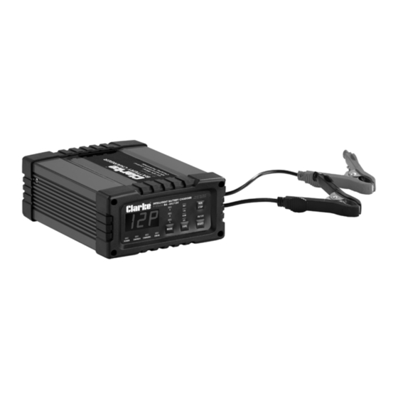
- Page 1 6V/12V INTELLIGENT BATTERY CHARGER MODEL NO: IBC8 PART NO: 6267035 OPERATION & MAINTENANCE INSTRUCTIONS ORIGINAL INSTRUCTIONS DL0721...
-
Page 2: Environmental Recycling Policy
GUARANTEE This CLARKE product is guaranteed against faulty manufacture for a period of 12 months from the date of purchase. Please keep your receipt as proof of purchase. -
Page 3: Specifications
SPECIFICATIONS Model Number IBC8 Input voltage / Current 230V, 50Hz Battery charging voltages: 6V & 12V Power 320W Max Output current 6V: 4A 12V:8A Charging steps 9 steps, (smart charger) Charging Battery Capacity 160 AH IP Rating IP40 Operating Temperature Range -20 to 50°C... - Page 4 Charging Clamp Negative (Black) 3 Control Buttons The IBC8 is designed for charging most types of 6V & 12V lead-acid, GEL, MF (Maintenance Free), Calcium and AGM (Absorbed Glass Mat) batteries. DO NOT use this product to charge other type of batteries like Nickel Cadmium (NiCad), Nickel-Metal Hydride (Ni-MH), Lithium-Ion, Dry Cell etc.
-
Page 5: Electrical Connections
ELECTRICAL CONNECTIONS WARNING! READ THESE ELECTRICAL SAFETY INSTRUCTIONS THOROUGHLY BEFORE CONNECTING THE PRODUCT TO THE MAINS SUPPLY. Before switching the product on, make sure that the voltage of your electricity supply is the same as that indicated on the rating plate. This product is designed to operate on 230VAC 50Hz. -
Page 6: Safety Precautions
SAFETY PRECAUTIONS WARNING: ALWAYS SWITCH OFF THE CHARGER WHEN CONNECTING OR DISCONNECTING LEADS TO AVOID SPARKING AS HIGHLY INFLAMMABLE HYDROGEN GAS CAN BE RELEASED IN THE PROCESS OF BATTERY CHARGING PLEASE READ BEFORE USING THIS UNIT 1. Batteries can generate explosive gases during normal operation. ALWAYS use in well ventilated area. - Page 7 Have it checked and repaired if damaged. 21. NEVER attempt any repairs yourself. If you have a problem with your charger contact your local CLARKE dealer or contact service@clarkeinternational.com 22. When charging is complete, ensure that the vehicle battery leads are secured to the proper terminals which should be clean, and lightly smeared with petroleum jelly to prevent corrosion.
-
Page 8: Charger Location
PREPARATION 1. It may be necessary to remove the battery from a vehicle to charge it. • ALWAYS remove the grounded terminal from the battery first. • Ensure all accessories in the vehicle are switched off to prevent sparking. 2. Clean the battery terminals. Be careful to keep any corrosive matter from coming in contact with eyes.If corrosive matter enters your eye, immediately flood eye with running clean cold water for at least 15 minutes and seek medical attention immediately. - Page 9 CONTROLS BATTERY CHARGE INDICATORS: 1. Power - A green LED illuminates to confirm power is being supplied to the battery charger. If it is the only LED illuminated, the charger is in “Maintain Mode”. 2. Charged - A green LED illuminates to signal that the battery is fully charged and may be disconnected for use.
- Page 10 MODE: 1. V - Displays the battery voltage prior to pressing RUN, and displays the actual charging voltage during each of the charging cycles. NOTE: Due to the pulse voltages applied during the desulphation mode, the displayed voltage may constantly change and cycle from 0 volts to 16 volts.
- Page 11 RUN/STOP After selecting the above parameters pressing the RUN/STOP button starts and stops the charger. After commencing a charge cycle, use this button to stop the charger to change any of the charge parameters, e.g. current or chemistry. Recommence the charge cycle by pressing the button. Parts &...
- Page 12 FEATURES MICROPROCESSOR TECHNOLOGY The latest technology in battery chargers converts 240VAC to DC charging power using electronic components, unlike traditional battery chargers that rely on large heavy transformers. This allows the charger to be lightweight and compact without sacrificing performance. to increase safety, polarity protection prevents the output leads from sparking due to accidental reverse connection of short circuit.
- Page 13 needed to balance cell voltages and/or remove unique sulphation barriers caused when calcium batteries have a high demand or are left discharged for a number of days. ADJUSTABLE CHARGE VOLTAGE The chargers output voltage (V) can be selected to suit the output voltage of the battery being charged, i.e.
- Page 14 NOTE: This feature may cause an increased charge time due to interruptions to the charge cycle. AUTOMATIC MULTI-CYCLE CONDITIONING If the battery will not hold a charge at the completion of the first cycle, the 9 stages of the cycle are automatically repeated for up to a further two times to achieve the battery’s maximum charge condition.
-
Page 15: Operation
OPERATION PLACEMENT/MOUNTING The charger is designed for indoor use only. The position selected for the charging of the battery must be cool, dry, clean and well ventilated, away from flammable goods and ignition sources. NOTE: When utilised in caravans, motorhomes, 4WD’s or similar, the charger should be placed or mounted in a well ventilated location and protected from rain, water or moisture at all times. - Page 16 Wiggle or swivel the clamps several times - this action ensures integrity of the connection and minimises sparks/arcing. b. Connection with the Battery Mounted in the Vehicle Determine if the vehicle is POSITIVELY (+) or NEGITIVELY (-) earthed. NOTE: The battery terminal NOT connected to the chassis MUST be connected to the battery charger first.
- Page 17 SELECT THE CHARGE VOLTAGE Press the “SELECT” button to select the appropriate battery voltage - 6V or 12V. The LCD will display 6P or 12P. SELECT THE BATTERY CHEMISTRY Press the “TYPE” button to select the appropriate battery chemistry and technology - WET, CALCIUM,AGM or GEL.
-
Page 18: Care & Maintanence
RECHECK THE ELECTROLYTE LEVELS Recheck the electrolyte levels and top up if required - this is especially necessary for Calcium type batteries. CARE & MAINTANENCE This battery charger requires minimal maintenance. As with any appliance or tool, a few common sense rules will prolong its working life. WARNING: ALWAYS BE SURE THE CHARGER IS UNPLUGGED BEFORE PERFORMING ANY MAINTENANCE OR CLEANING. -
Page 19: Parts Diagram
PARTS DIAGRAM PARTS LIST ESCRIPTION ESCRIPTION Charging Cables & Clamps Power Cable Aluminium Case Bottom Case Panel Back Panel Screw, M3 x 5 Screws, ST3 x 10 Front Panel Screws, M3 x 14 Display Board Printed Circuit Board Assembly Parts & Service: 020 8988 7400 / E-mail: Parts@clarkeinternational.com or Service@clarkeinternational.com... - Page 20 CHARGE CYCLES TAGE UNCTION ESCRIPTION Diagnosis To determine whether the battery is defective. Charging will not proceed if the battery voltage is <0.5V and an error code will be displayed on the LCD. Desulphation This stage provides a stepped or pulsed voltage to help remove the sulphation of plates which can occur when the battery is left discharged for prolonged periods.
- Page 21 TAGE UNCTION ESCRIPTION Bulk Charge Initially, maximum current is applied to the battery (Constant however, the three phases of the stage reduce the Current) time to charge, control electrolytic loss and enhance battery health and life. CC1 - Charging at maximum current. CC2 - Current is reduced.
- Page 22 DECLARATION OF CONFORMITY - UKCA Parts & Service: 020 8988 7400 / E-mail: Parts@clarkeinternational.com or Service@clarkeinternational.com...
-
Page 23: Declaration Of Conformity (Ce)
DECLARATION OF CONFORMITY - CE Parts & Service: 020 8988 7400 / E-mail: Parts@clarkeinternational.com or Service@clarkeinternational.com...
Need help?
Do you have a question about the IBC8 and is the answer not in the manual?
Questions and answers