
Related Manuals for Clarke WBC400


Summary of Contents for Clarke WBC400
- Page 1 BATTERY CHARGER-STARTER MODEL NO: WBC240 & WBC400 PART NO: 6261505 & 6261515 OPERATION & MAINTENANCE INSTRUCTIONS GC0116...
-
Page 2: Environmental Recycling Policy
Battery Charger will give you long and satisfactory service. GUARANTEE This CLARKE product is guaranteed against faulty manufacture for a period of 12 months from the date of purchase. Please keep your receipt as proof of purchase. -
Page 3: Specifications
SPECIFICATIONS Model Number WBC240 WBC400 Dimensions (D x W x H) 274 x 370 x 590 390 x 442 x 631 Weight 14.8 kg 24.65 kg IP Rating IP20 Suitable Battery Type Lead Acid, GEL, WET, AGM with 12/24 voltages... -
Page 4: Safety Precautions
SAFETY PRECAUTIONS WARNING: HIGHLY INFLAMMABLE HYDROGEN GAS IS RELEASED IN THE PROCESS OF BATTERY CHARGING. ALWAYS REMEMBER TO SWITCH OFF THE CHARGER/STARTER FIRST TO AVOID SPARKING. PLEASE READ BEFORE USING THIS UNIT 1. Battery acid is very corrosive. If spilled, clean the area immediately and wash with water. -
Page 5: Electrical Connections
The maximum input current for the WBC240 (24V output) is 39 amps with a duty cycle of 3 secs on/120 secs off. The maximum input current for the WBC400 (24V output) is 75 amps with a duty cycle of 3 secs on/120 secs off. -
Page 6: Wbc240 Overview
WBC240 OVERVIEW 1 Fuse Holder Power On/Off Switch 2 Charging condition meter (Amps) Positive Terminal +24V 3 High/Low Charging Selector Positive Terminal +12V 4 Min/Boost Charge Charging Selector Negative (BLACK) lead 5 Battery Charge/Jump Start Mode 10 Positive (RED) lead Selector switch The WBC240 is provided with a pair of leads complete with clamps for connection to a battery via the appropriate outlet connections - 12V and 24V,... -
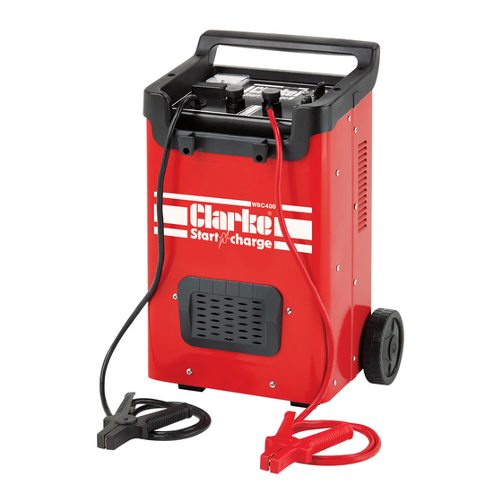
Page 7: Wbc400 Overview
5 Charging Mode Indicator 11 Positive (RED) lead 6 Charging Level Selector The WBC400 is provided with a pair of leads complete with clamps for connection to a battery via the appropriate outlet connections (12V and 24V), as shown. Two selector switches provide for different functions as shown above. The main fuse is mounted on the front panel, as shown and the model incorporates a thermal overload cut-out. - Page 8 ASSEMBLY ASSEMBLY 1. Pass the axle through the holes in the body of the machine and fit circlips to the axle at the position shown. 1. Slide the wheels onto each end of the axle and secure with further circlips outside each wheell. 2.
-
Page 9: General Preparation
GENERAL PREPARATION CHARGER LOCATION 1. Place the charger as far away from the car battery as possible. 2. Do not position the charger above the battery during the charging procedure. Gases from the battery will cause corrosion and damage the charger. -
Page 10: Connecting To A Battery
CONNECTING TO A BATTERY WARNING: A SPARK NEAR THE BATTERY MAY CAUSE BATTERY EXPLOSION. TO REDUCE THE RISK OF A SPARK NEAR THE BATTERY: • Turn off the charger before you connect/disconnect the DC output connectors. • Do not let the connectors touch each other. •... -
Page 11: Battery Charging
BATTERY CHARGING CHARGING A BATTERY INSTALLED IN THE VEHICLE 1. Arrange the leads carefully to reduce the risk of damage caused by sharp edges. 2. Check the polarity of the battery posts. 3. Consult the vehicle manual to confirm if the vehicle has a Negative or Positive earth. -
Page 12: Rapid Charging Using The Timer
24V terminal. RAPID CHARGING USING THE TIMER 1. The WBC400 has a charge timing device of up to 60 minutes operation. 2. To initiate Rapid Charging, turn the fast-charge timer to the required charging time in minutes... -
Page 13: Operation Of The Charger
• Medium charging rate:- MIN and 2. 3. High charging rate:- BOOST. (this over-rides the 1/2 switch) WBC400 MODEL 1. Set the mode rotary switch to the CHARGE function indicated by the battery symbol. Set the switch to low (1-3) or High (4-6) as required. -
Page 14: When Charging Is Complete
• Charge a sealed battery very slowly, monitoring the voltage across the battery terminals using a voltmeter. • When the battery terminal voltage reaches 14.4V for 12V batteries, stop charging. WHEN CHARGING IS COMPLETE 1. When charging is complete the ammeter reading should be close to “0” and the electrolyte in the battery may begin to gas. -
Page 15: Procedure For Engine Starting
MIN position. 4. Connect the cables to the vehicle battery as for charging. 5. Set the ON/OFF switch to ON. WBC400 MODELS 1. Set the rotary CHARGE/START switch in the START position. 2. Connect the cables to the vehicle battery as for charging. -
Page 16: Thermal Cutout
• Short Circuit - clamps touch or cross connection to battery. • Prolonged starting attempts. REPLACING THE FUSE The fuse fitted is rated at 2 x 60A (WBC240) and 2 x 100A (WBC400) and is fitted behind the clip-on cover for easy replacement. 1. Switch the unit off and disconnect from the mains. - Page 17 MAINTANENCE This charger requires minimal maintenance. As with any appliance or tool, a few common sense rules will prolong the life of the battery charger. WARNING: ALWAYS BE SURE THE CHARGER IS UNPLUGGED FROM THE MAINS AND ANY BATTERY BEFORE PERFORMING ANY MAINTENANCE OR CLEANING.
-
Page 18: Troubleshooting
Bad Battery light The battery voltage is Have the battery tested by comes on between 0.5V and 1.5V. a qualified technician; (WBC400 model) The battery voltage is lower Replace the bad battery if than 11V, after being necessary. charged for 4 minutes. -
Page 19: Declaration Of Conformity
DECLARATION OF CONFORMITY Parts & Service: 020 8988 7400 / E-mail: Parts@clarkeinternational.com or Service@clarkeinternational.com... -
Page 20: Wbc240 Parts Diagram
WBC240 PARTS DIAGRAM Parts & Service: 020 8988 7400 / E-mail: Parts@clarkeinternational.com or Service@clarkeinternational.com... -
Page 21: Wbc240 Parts List
WBC240 PARTS LIST NO DESCRIPTION NO DESCRIPTION Thermostat Varistor Front Handle Resistor Selector Switch Diverter On/Off Switch Fuse Cover Ammeter Fuse Power Cable Rectifier Bridge Earth Clamp (black) Cable Gland Live Clamp (Red) Transformer Wheel Back Panel Axle Bottom Panel Circlip Foot Fuse Post... -
Page 22: Wbc400 Parts Diagram
WBC400 PARTS DIAGRAM Parts & Service: 020 8988 7400 / E-mail: Parts@clarkeinternational.com or Service@clarkeinternational.com... -
Page 23: Wbc400 Parts List
WBC400 PARTS LIST ESCRIPTION ESCRIPTION Earth Clamp (Black) Axle Positive Clamp (Red) Base Panel Handle Foot Bracket Fuse Cover Wheel Cable Insert Diverter Ammeter Circlip Back Panel Plastic Ventilation Grill Fuse Thermostat Terminal Resistor Indicator Light Varistor Top Panel Capacitor...
Need help?
Do you have a question about the WBC400 and is the answer not in the manual?
Questions and answers