
Related Manuals for Clarke IBC20


Summary of Contents for Clarke IBC20
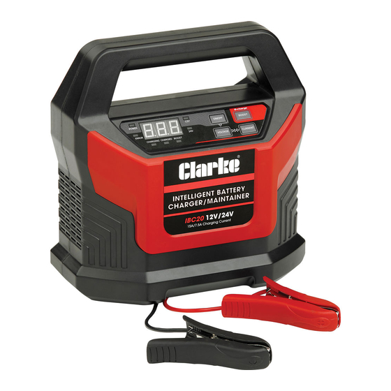
- Page 1 INTELLIGENT BATTERY CHARGER/MAINTAINER MODEL NO: IBC20 PART NO: 6267012 OPERATION & MAINTENANCE INSTRUCTIONS ORIGINAL INSTRUCTIONS GC0918 - ISS 1...
-
Page 2: Environmental Recycling Policy
GUARANTEE This CLARKE product is guaranteed against faulty manufacture for a period of 12 months from the date of purchase. Please keep your receipt as proof of purchase. -
Page 3: Safety Precautions
6. Never touch the negative and positive leads together. 7. Never attempt any repairs yourself. If you have a problem with your charger contact your local Clarke dealer or contact Service@Clarkeinternational.com 8. When charging is completed, ensure that the vehicle battery leads are secured to the proper terminals which should be clean, and lightly smeared with petroleum jelly to prevent corrosion. -
Page 4: Electrical Connections
ELECTRICAL CONNECTIONS WARNING! READ THESE ELECTRICAL SAFETY INSTRUCTIONS THOROUGHLY BEFORE CONNECTING THE PRODUCT TO THE MAINS SUPPLY. Before switching the product on, make sure that the voltage of your electricity supply is the same as that indicated on the rating plate. This product is designed to operate on 230VAC 50Hz. - Page 5 6 NEGATIVE (BLACK) lead 13 POSITIVE (RED) lead 7 Digital Display The IBC20 is designed for charging all types of 12V and 24V lead-acid batteries including WET (flooded), GEL, MF (Maintenance Free), EFB (Enhanced flooded battery), and AGM (Absorbed Glass Mat) batteries.
-
Page 6: Charger Location
Once connected, the charger will begin charging after approx 5 seconds. The yellow CHARGE LED will be on during charging and this will be replaced by the FULL LED when charging is completed. If the charger remains connected, it will automatically switch from charging to maintenance status to maintain the batteries during periods of storage. -
Page 7: Connecting To A Battery
3. Do not let battery acid drip on the charger when reading a hydrometer for specific gravity or when you fill the battery. 4. Do not use the charger in an enclosed space with reduced airflow. CONNECTING TO A BATTERY WARNING: A SPARK NEAR THE BATTERY MAY CAUSE BATTERY EXPLOSION. -
Page 8: The Charging Process
3. Reach over and connect the NEGATIVE (BLACK) lead at arms length to the NEGATIVE post on the battery. 4. When charging is completed, switch off the charger and disconnect the plug from the power supply. When you disconnect the charger from the battery always do it in the opposite order to the sequence of connection. -
Page 9: Charging Settings
CHARGING SETTINGS The IBC20 has the following selectable charging settings: POWER BOOST DISPLAY EXPLANATION LIGHT LIGHT STANDBY ---------- Blinks Unit not charging or providing any power. If you want charging to pause, press the ON/OFF button & the unit will enter standby mode. -
Page 10: Using The 12V Boost Function
POWER BOOST DISPLAY EXPLANATION LIGHT LIGHT 24V/7.5A 7.5A Blue Press the VOLTAGE button to select 24V, then press the CURRENT button repeatedly until 7.5A is shown. This mode is recommended for 25- 200 AH batteries. BOOST When connected to the battery, unit 12V/20A can enter BOOST mode by pressing the BOOST button. -
Page 11: Charging Time Duration
• E03: Inappropriate charge mode (12V mode chosen for 24V battery) • E04: Battery defective, battery cannot retain charge • E05: Unsuccessful desulphation (Defective battery) • E06: Reverse connection (with error LED) CHARGING TIME DURATION Different battery capacity, residual voltage and charging current will all affect charging time. -
Page 12: Troubleshooting
TROUBLESHOOTING Problem Cause Solution ERROR display E01 High temperature After the internal (with buzzer) temperature reduces the charger will automatically start charging again. ERROR display E02 1) Open circuit 1) Connect the red and 2) Dirty battery posts black clamps or ring 3) Dead battery terminals to the battery posts 4) Output short circuit... -
Page 13: Care & Maintanence
2. Clean the case and leads if necessary with a moist cloth and clean any corrosion from the clamps with a solution of water and baking soda. SPECIFICATIONS Model Number IBC20 Input voltage/current 230V, 50Hz, 2.5A Battery charging voltages: 12V & 24V... -
Page 14: Component Parts
COMPONENT PARTS ESCRIPTION ESCRIPTION Front Panel Power Cable Front Cover Extension Cable Screw Nuts Function Panel Fan Assembly Locking Buckle Partition Assembly Circuit Board Control Module Machine Screw Screws Screw Main Circuit Board Back Cover Clip Parts & Service: 020 8988 7400 / E-mail: Parts@clarkeinternational.com or Service@clarkeinternational.com... -
Page 15: Declaration Of Conformity
DECLARATION OF CONFORMITY Parts & Service: 020 8988 7400 / E-mail: Parts@clarkeinternational.com or Service@clarkeinternational.com...
Need help?
Do you have a question about the IBC20 and is the answer not in the manual?
Questions and answers