
Related Manuals for GE PDM


Summary of Contents for GE PDM
- Page 1 GE Healthcare Patient Data Module (PDM) Service Manual Software version 1 Patient Data Module English 2030048-001 (cd) 2030046-001A (paper) © 2007 General Electric Company. All rights reserved.
- Page 2 Technologies registered in the United States Patent and Trademark Office. CARESCAPE is a trademark of GE Medical Systems Information Technologies. For technical documentation purposes, the abbreviation GE is used for the legal entity name, GE Medical Systems Information Technologies. Patient Data Module...
-
Page 3: Table Of Contents
Contents Introduction ....... . 1-1 Manual information ..........1-2 Revision history . - Page 4 Connect to host patient monitor ........3-5 Connect to transport bedside monitor .
- Page 5 Troubleshooting ......6-1 Overview............6-2 Required tools and equipment .
- Page 6 Appendix B– Electromagnetic Compatibility ..B-1 Electromagnetic compatibility (EMC) ......B-2 Guidance and manufacturer’s declaration –...
-
Page 7: Introduction
Introduction 2030047-001A Patient Data Module... -
Page 8: Manual Information
Ordering manuals A paper copy of this manual will be provided upon request. Contact your local GE representative and request the part number on the first page of the manual. Safety information... -
Page 9: Hazard Definitions
Introduction Contact GE for information before connecting any devices to the equipment that are not recommended in this manual. Parts and accessories used must meet the requirements of the applicable IEC 60601 series safety standards, and/or the system configuration must meet the requirements of the IEC 60601 medical electrical systems standard. -
Page 10: Patient Data Module Hazards
Introduction Patient Data Module hazards WARNING ACCIDENTAL SPILLS—To avoid electric shock or device malfunction liquids must not be allowed to enter the device. If liquids have entered a device, take it out of service and have it checked by a service technician before it is used again. Equipment symbols The following symbols appear on the equipment. -
Page 11: Service Information
Any unauthorized attempt to repair equipment under warranty voids that warranty. It is the user’s responsibility to report the need for service to GE Medical Systems Information Technologies or to one of their authorized agents. Failure on the part of the responsible individual, hospital, or institution using this equipment to implement a satisfactory maintenance schedule may cause undue equipment failure and possible health hazards. -
Page 12: Equipment Identification
Introduction Equipment Identification Every GE Medical Systems Information Technologies device has a unique serial number for identification. A sample of the information found on a serial number label is shown below. ### ## ## #### # # Description Product code... -
Page 13: Equipment Overview
Equipment Overview 2030047-001A Patient Data Module... -
Page 14: Overview
Equipment Overview Overview The Patient Data Module is a data acquisition device for a GE modular system. It provides a connection from the host monitor to the patient, processes the patient data signals and stores a limited amount of patient data (24 hours captured at 1 minute resolution) for seamless transport. -
Page 15: Rear View
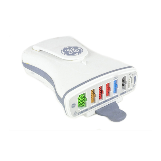
Equipment Overview Rear view 405B ePort host interface connection Battery door Side view 406A Expansion cover Docking station Pull tab 2030047-001A Patient Data Module... -
Page 16: Controls
Equipment Overview Controls The power/zero all key has a dual role as a power on and zero all. Power on — Turns the data acquisition function ON. Power is derived from a battery or patient monitor. When turned on, the function changes to the zero all function. -
Page 17: Basic Components
Equipment Overview Basic components Battery The Patient Data Module is designed to operate on battery power when used with a transport monitor or whenever AC power is interrupted. A complete battery management system allows you to obtain maximum battery performance. When connected to a bedside monitor, audible and visual alarms alert you when loss of power is imminent, and on-screen capacity gauges on the transport monitor indicate battery charge condition and capacity. - Page 18 Equipment Overview Views Patient Data Module bedside dock. 480A Patient Data Module fixed mount adapter (mini dock). 481A Patient Data Module 2030047-001A...
-
Page 19: Theory Of Operation
Equipment Overview Theory of operation Overview The Patient Data Module is a portable acquisition device. It collects data from a patient, converts the data to a digital form for processing, and sends the data to a bedside, transport or surgical monitor for further processing and display. The data that it collects, converts, and sends includes the patient’s vital signs and physiological waveforms. - Page 20 Equipment Overview Up to four channels of invasive blood pressure and cardiac output or two channels of temperature. Defibrillator sync/analog out interface Patient Data Module 2030047-001A...
-
Page 21: Installation
Installation 2030047-001A Patient Data Module... -
Page 22: Battery
Installation Battery Test the battery charge Before installing a battery, verify the battery’s state of charge. Press the green TEST button on the battery. The number of charge level indicator LEDs that illuminate measures the approximate charge remaining in the battery. Four LEDs illuminated: 75% –... -
Page 23: Software
Software The Patient Data Module leaves the factory with software installed. If you need to install the software, contact your GE representative. Mounting options WARNING For safety reasons, all connectors for patient cables and sensor leads are designed to prevent inadvertent disconnection, should someone pull on the leads. - Page 24 Installation 482A Mounting options include mounting to a bed headboard or footboard, an IV pole, or a roll stand using one of the docking stations. Mounting kits include all necessary hardware and installation instructions. 483A Patient Data Module 2030047-001A...
-
Page 25: Connect To Host Patient Monitor
Installation Connect to host patient monitor Connect to transport bedside monitor If using the Patient Data Module with a transport bedside monitor, Guide the mounting rails of the Patient Data Module onto the transport dock mounting rails. Slide the Patient Data Module toward the ePort until the locking key secures it to the transport dock. - Page 26 Installation Patient Data Module 2030047-001A...
-
Page 27: Service Tool And Configuration
Service Tool and Configuration 2030047-001A Patient Data Module... -
Page 28: Overview
Category 5 crossover cable (2028822-001) ePort to host interface cable (2017098-002) Solar 8000M/i patient monitor with PDM service adapter (2028845-002) Patient Data Module software CD with GEHC MS Service Tool If servicing the Patient Data Module without a host patient monitor:... - Page 29 Connect the ePort to host interface cable between the ePort on the Patient Data Module and the ePort connector on the PDM service adapter. If the PDM service adapter is not connected to a Solar 8000M/i patient monitor, connect the external power supply to the PDM service adapter.
-
Page 30: Change The Pc's Ip Address
Service Tool and Configuration Change the PC’s IP address NOTE Disable all network ports on the PC except the Patient Data Module connection. Windows XP Windows 2000 From the toolbar, select Start > Run Type cmd and press Enter. Type ipconfig<space>/all and press Enter. If the IP address and subnet mask are defined, record them: IP address: _______________________________________ Subnet mask: _________________________________________... - Page 31 Service Tool and Configuration 455A In the specific service (e.g. BlackICE and Security Accounts Manager) properties window, select Stop. Click Stop 456A Verify that the Service status reads Stopped. 2030047-001A Patient Data Module...
-
Page 32: Enter The Patient Data Module Service Tool
Service Tool and Configuration Verify Stopped 432A To disable the Security Accounts Manager, select Disable from the Startup type drop down list. Select Apply to disable the Security Accounts Manager. Select Ok and close all windows. Repeat these steps for all VPN, wireless network cards or any firewall protection programs running on your PC. -
Page 33: Service Tool Modules
Service Tool and Configuration NOTE Username and password are case sensitive. Username and password cannot be created, edited or deleted. 433A Service tool modules The GEHC MS Service Tool has four categories; Device Information, Configuration, Diagnostics, and Calibration. Each category contains module(s) for servicing the Patient Data Module. -
Page 34: Configuration
Service Tool and Configuration 434A Configuration The Configuration category consists of Asset Settings, ECG Filter Config, Licensing and Software Transfer modules. Asset Settings The Asset Settings module displays the manufacturer’s serial number and the user assigned asset number. Enter the serial number and click Submit. NOTE The manufacturer’s serial number must follow the specific format found on the serial number label on the Patient Data Module. - Page 35 Licensing The Licensing module is used for activating or removing license(s). To obtain a license, contact GE technical support and provide the Patient Data Module serial number and MAC address. See the “How to Reach Us...” page included with this manual for contact information.
-
Page 36: Diagnostics
If a value in the Service Metrics module is out of specification, the data field will be highlighted red. Contact GE technical support. See the “How to Reach Us...” page included with this manual for contact information. - Page 37 Service Tool and Configuration Measure voltages indicated below using the digital voltmeter. 435A To calibrate Analog-Out ECG, measure voltage across the following pins. Wire color Signal name Brown ECG_ANALOG_OUT Green ANALOG_RETURN To calibrate Analog-Out IP, measure voltage across the following pins. Wire color Signal name BP_ANALOG_OUT...
- Page 38 Service Tool and Configuration 4-12 Patient Data Module 2030047-001A...
-
Page 39: Maintenance
Maintenance 2030047-001A Patient Data Module... -
Page 40: Maintenance Schedule
Maintenance Maintenance schedule Manufacturer recommendations To help ensure the equipment remains in proper operational and functional order, adhere to a good maintenance schedule. The manufacturer recommends that the following be performed by service personnel upon receipt of the equipment, every 12 months thereafter, and every time the unit is serviced: Visual inspection Cleaning... -
Page 41: Cleaning
Maintenance Cleaning Precautions Improper cleaning methods can result in degradation of the equipment performance and/or failure. To avoid damage to the equipment: Never use conductive solutions, solutions that contain chlorides, wax, or wax compounds to clean the equipment. Never immerse equipment in any liquid. Never pour or spray any liquid on the equipment or permit fluid to seep into connections or openings. -
Page 42: Storage
Maintenance Dry thoroughly with a clean, dry, lint-free cloth and let air dry for at least 30 minutes. Do not apply heat. NOTE Drying times may vary based on the environmental conditions. Storage Remove batteries when the device is not in use, even for short periods of time. Store in a dry well-ventilated area. -
Page 43: Expansion Interface Cleaning
Maintenance Expansion interface cleaning Under normal operation, the expansion interface should not require cleaning. If the expansion interface does require cleaning, follow these instructions. CAUTION The expansion interface is not waterproof. Do not let fluids enter the electronics through the expansion interface. -
Page 44: Battery Compartment Cleaning
Maintenance Wipe off cleaning solution with a clean, moist swab. Dry thoroughly with a clean, dry, swab and let air dry for at least 30 minutes. Do not apply heat. NOTE Drying times may vary based on the environmental conditions. Battery compartment cleaning Under normal operation, the battery compartment should not require cleaning. -
Page 45: Battery Care
This is a percent of full charge capacity. Use recommendations GE recommends the following methods to improve battery performance: Location — Position the equipment in a location that does not artificially increase the operating temperature of the batteries. -
Page 46: Charge The Battery
The battery is then recharged to 100% resulting in a 95% average state of charge. Storing the battery at a high state of charge also reduces the life of the battery. GE recommends that you remove the battery and store it near the Patient Data Module until it is needed. -
Page 47: Checkout Procedures And Nbp Calibration
1-800-8-BATTERY (800-822-8837) internet: www.rbrc.org Checkout procedures and NBP calibration GE recommends that qualified service personnel perform system checkout procedures (including electrical safety tests, parameter tests, and NBP calibration) found in the Solar 8000M/i patient monitor service manual: upon receipt of the equipment,... - Page 48 Maintenance 5-10 Patient Data Module 2030047-001A...
-
Page 49: Troubleshooting
Troubleshooting 2030047-001A Patient Data Module... -
Page 50: Overview
Patient Data Module software CD with GEHC MS service tool (shipped with Patient Data Module) Solar 8000M/i patient monitor with PDM service adapter (2028845-002) PC with Microsoft Windows XP or 2000 operating system, a CDROM drive, and a network card... -
Page 51: Problems And Solutions
Check for cracks or other damage to the bottom housing. If damaged, contact GE technical support to service the Patient Data Module. See the “How to Reach Us...” page included with this manual for contact information. - Page 52 Solar 8000M/i patient monitor service manual Troubleshooting chapter for further information. Check for damage to the ePort interface on the Patient Data Module. If damaged, contact GE technical support to service the Patient Data Module. See the “How to Reach Us...” page included with this manual for contact information.
-
Page 53: Error Messages
Patient Data Module. Error message Action COMMUNICATION Go to See Problems and solutions on page 6-3. FAILURE BATTERY FAIL Go to See Battery care on page 5-7. SERVICE THE PDM Contact GE technical support. 2030047-001A Patient Data Module... - Page 54 Troubleshooting Patient Data Module 2030047-001A...
-
Page 55: Field Replaceable Units
Field Replaceable Units 2030047-001A Patient Data Module... -
Page 56: Ordering Parts
Ordering Parts The parts lists in this chapter supply enough detail for you to order replaceable parts. If you require additional information or troubleshooting assistance, contact GE Technical Support. To order parts, contact Service Parts at the address or telephone number listed on the “How to Reach Us...”... -
Page 57: Disassembly Guidelines
Patient Data Module. NOTE GE recommends using the new fasteners (screws, washers, etc.) provided in the FRU kits rather than re-using the old fasteners. Some fasteners are not intended to be re-used more than three times. -
Page 58: Replacement Procedures
Field Replaceable Units The following guidelines may not guaranty a 100% static-free workstation, but can greatly reduce the potential for failure of any electronic assemblies being serviced: Discharge any static charge you may have built up before handling semiconductors or assemblies containing semiconductors. A grounded, antistatic wristband (3M part number 2046 or equivalent) or heel strap should be worn at all times while handling or repairing assemblies containing semiconductors. - Page 59 Field Replaceable Units 855A Press the battery door closed until it seals the battery compartment. WARNING PHYSICAL INJURY—Make sure the battery is completely inserted and that the battery door is securely sealed. Falling batteries could seriously or fatally injure neonatal or other vulnerable patients.
-
Page 60: Labels
Field Replaceable Units Labels Apply labels as shown. 404B 464A Battery door and tray Remove 1 screw that holds the battery door to the housing and remove the door and washer. screw 462A Remove the battery if one is in the tray. Use a flathead screw driver to lift the catch tab on the tray as you pull it out of the housing. -
Page 61: Mount Rail And Pull Tab
Field Replaceable Units catch tab 468A Mount rail and pull tab Remove 2 screws on the latch stop. Remove the latch stop. Latch stop screws 463A Grasp the pull tab between thumb and index finger as shown and gently pull it straight out about a half inch. - Page 62 Field Replaceable Units 469A NOTE In the event that the pull tab assembly comes apart when pulled from the rail slot, reassemble as shown below. 470A 471A Remove 2 short screws at the rear of the mount rail and 2 long screws at the front of the mount rail.
-
Page 63: Top Housing
Field Replaceable Units NOTE When reassembling, make sure there are not gaps between the mount rail and the housing when re-seating. Top housing Remove the mount rail and pull tab per above steps. Remove 4 machine screws that hold the top and bottom housing together. 464A Turn the Patient Data Module right side up and lift off the top housing. - Page 64 Field Replaceable Units Front panel connector 473A Starting at the rear of the module, position alignment pins of the top housing into the bottom housing holes, then close the housing straight down. Alignment pins 474A Squeeze the top and bottom housings together to eliminate gaps. Install the screw near the Power ON button first.
-
Page 65: Main Board
Field Replaceable Units Main board Remove the top housing per above steps. Disconnect the NIBP cable from the connector without pulling on the wires. Alignment pins NIBP cable 465A Remove 6 screws on the main board. Remove the main board. NOTE When installing the main board, position it into the alignment pins, (See figures above and below.) fold the flex material over the top of the board and... -
Page 66: Nbp Hose, Coupling And Elbow
Field Replaceable Units Licensing information must be re-entered. Contact GE technical support and provide the Patient Data Module serial number and MAC address to proceed. See the “How to Reach Us...” page included with this manual for contact information. Go to Licensing on page 4-9 for instructions on entering the new activation code. -
Page 67: Nbp Assembly With Manifold Hose
Field Replaceable Units NBP assembly with manifold hose Remove the top housing, main board, NBP hose, coupling and elbow per above steps. Remove 4 screws from the battery cover. Battery cover Front panel board connector Main board flex pump connector 467A Grasp and slide the battery cover out to the rear. - Page 68 Field Replaceable Units Interface gasket 478A Before installing the NBP assembly with manifold: Make sure the pump and manifold are fully seated together. Make sure the gasket is in place. Position the manifold and pump in the bottom housing and carefully press to seat connector.
-
Page 69: A Appendix A-Technical Specifications
Appendix A–Technical Specifications 2030047-001A Patient Data Module... -
Page 70: Technical Specifications
Appendix A–Technical Specifications Technical Specifications Physical Height: 7.0 cm (2.75 in) Width: 14.6 cm (5.75 in) Depth: 21.6 cm (8.5 in) Weight: 1.1 kg (2.5 lbs.) without optional battery 1.3 kg (2.8 lbs.) with optional battery Environmental Power requirements Input voltage: 8 to 17 Vdc Input current: 0.3A nominal at 16.75 V... -
Page 71: Ecg
Appendix A–Technical Specifications Standard leads available: I, II, III, V1 to V6, aVR, aVL, and aVF Leads analyzed Twelve (I, II, III, V1 to V6, aVR, aVL, and aVF) simultaneously: Lead fail: Identifies failed electrodes and switches to those intact Lead fail sensing current: Active electrodes: <30 nA each Reference electrode: <270 nA... - Page 72 Appendix A–Technical Specifications Heart rate Heart rate averaging: 8 / 4 beats Display update interval: 2 seconds Heart rate accuracy: ± 1% or ± 1 beat/minute, whichever is greater Response time: < 6 seconds Limit alarm delay: <10 seconds after limit alarm condition exceeded Heart rate alarm range: 0 to 300 beats/minute, high limit >...
-
Page 73: Respiration
Appendix A–Technical Specifications Respiration Respiration range limit: 1 to 200 breaths/minute Respiration rate accuracy 0 to 120 breaths/minute ± 1 121 to 200 breaths/minute ± 3 Impedance range: 100 to 1500 Ohms at 52.6 KHz Detection sensitivity range: 0.4 to 10 Ohms impedance variation Respiration rate alarm 1 to 200 breaths/minute range:... -
Page 74: Invasive Blood Pressure
Appendix A–Technical Specifications Invasive blood pressure Number of channels: Up to 4 (with appropriate cables) Transducer sites, site name arterial (ART): systolic, diastolic, mean and rate and displayed values: femoral (FEM): systolic, diastolic, mean and rate pulmonary artery (PA): systolic, diastolic and mean central venous pressure (CVP): mean left atrial (LA): mean right atrial (RA): mean... -
Page 75: Non-Invasive Blood Pressure
Appendix A–Technical Specifications Output specifications Frequency response: dc to 40 Hz (+0/-3 dB) Zero balance range: ±150 mmHg Zero balance accuracy: ±1 mmHg Accuracy: ±2% or ±1 mmHg, which ever is greater (exclusive of transducer) Displayed frequency response: 0 to 12 Hz or 0 to 40 Hz (-3dB) user-selectable Display scale selections: 0-30, 0-40, 0-60, 0-100, 0-160, 0-200, 0-300 mmHg Analog output:... - Page 76 Appendix A–Technical Specifications Systolic pressure range Adult: 30 to 290 mmHg Pediatric: 30 to 240 mmHg Neonatal: 30 to 140 mmHg Diastolic pressure range Adult: 10 to 220 mmHg Pediatric: 10 to 200 mmHg Neonatal: 10 to 110 mmHg Mean pressure range Adult: 20 to 260 mmHg Pediatric: 20 to 215 mmHg Neonatal: 20 to 125 mmHg...
-
Page 77: Pulse Oximetry (Sp02
Appendix A–Technical Specifications Pulse oximetry (Sp02) Parameters monitored: Arterial oxygen saturation (SpO2) and peripheral pulse rate (PPR) Probe types: Masimo (reusable/single use) Nellcor (reusable/single use) Masimo range SpO2: 1 to 100% Pulse rate: 25 to 240 beats per minute Masimo accuracy 70 to 100% SpO2: ±2 <69% SpO2: Unspecified ±3 beats per minute without motion... -
Page 78: Cardiac Output
Appendix A–Technical Specifications Cardiac output Method: Thermodilution Parameters Displayed: Cardiac output, blood temperature, injectate temperature, real-time cardiac output washout curve, last average CO Cardiac output range: 0.2 to 15 liters per minute Blood temperature range: 17°C to 42°C (62°F to 107°F) Blood temperature ±0.5°C 17°C to 30°C accuracy:... -
Page 79: Warranty
Appendix A–Technical Specifications Warranty One year warranty 2030047-001A Patient Data Module A-11... - Page 80 Appendix A–Technical Specifications A-12 Patient Data Module 2030047-001A...
-
Page 81: Appendix B- Electromagnetic Compatibility
Appendix B– Electromagnetic Compatibility 2030047-001A Patient Data Module... -
Page 82: Electromagnetic Compatibility (Emc
Appendix B– Electromagnetic Compatibility Electromagnetic compatibility (EMC) Changes or modifications to this system not expressly approved by GE can cause EMC issues with this or other equipment. This system is designed and tested to comply with applicable regulation regarding EMC and must be installed and put into service according to the EMC information stated in this appendix. -
Page 83: Guidance And Manufacturer's Declaration - Electromagnetic Immunity
Appendix B– Electromagnetic Compatibility Guidance and manufacturer’s declaration – electromagnetic immunity The Patient Data Module is intended for use in the electromagnetic environment specified below. It is the responsibility of the customer or user to assure that the Patient Data Module is used in such an environment. Immunity Test EN 60601 Test Level Compliance Level... -
Page 84: Recommended Separation Distances
Appendix B– Electromagnetic Compatibility Immunity Test EN 60601 Test Level Compliance Level Electromagnetic Environment – Guidance Portable and mobile RF communications equipment should not be used closer to any part of the equipment, including cables, than the recommended separation distance calculated from the equation applicable to the frequency of the transmitter. -
Page 85: Compliant Cables And Accessories
The table below lists cables, transducers, and other applicable accessories with which GE claims EMC compliance. NOTE Any supplied accessories that do not affect EMC compliance are not included. - Page 86 Appendix B– Electromagnetic Compatibility Category Description Maximum Lengths Care cable, ECG 3-lead Multi-Link w/grabber 3.6 m / 12 ft Care cable, ECG 3/5-lead Multi-Link 3.6 m / 12 ft Care cable, ECG 3-lead Multi-Link din, neonatal 3.6 m / 12 ft Care cable, ECG 6-lead Multi-Link 3.6 m / 12 ft Care cable, ECG 12-lead Multi-Link...
- Page 87 Care cable, temp single to disp 400/700 series 3.6 m / 12 ft SpO2 cables and sensors Cable Masimo LNC-10 GE connector 3.0 m / 9.8 ft Patient adapter cable - Nellcor DIGICAL - 3m (one wire 3.0 m / 0.8 ft...
- Page 88 Appendix B– Electromagnetic Compatibility Category Description Maximum Lengths Masimo reusable sensor, finger Masimo sensor LNCS Adtx adult adhesive Masimo sensor LNCS Pdtx PED adhesive Masimo sensor LNCS Inf-L infant adhesive Masimo sensor LNCS Neo-L neonatal adhesive Masimo sensor LNCS NeoPt-L NEOPT neonatal adhesive Masimo sensor LNCS DCI adult reusable Masimo sensor LNCS DCIP ped reusable...
- Page 89 Appendix B– Electromagnetic Compatibility Category Description Maximum Lengths Nellcor OxiMax adhesive sensor, pediatric Nellcor OxiMax adhesive sensor, infant Nellcor OxiMax adhesive sensor, neonatal Nellcor OxiMax adhesive sensor, nasal SC-PR Nellcor SoftCare nonadhesive sensor, neonate Nellcor SoftCare nonadhesive sensor, adult Nellcor Durasensor DS-100A finger-clip sensor, reusable adult Nellcor Oxiband OXI-A/N, adult, neonatal, reusable Nellcor Oxiband OXI-P/I, pediatric/infant, reusable...
- Page 90 Appendix B– Electromagnetic Compatibility B-10 Patient Data Module 2030047-001A...
- Page 92 + 86 21 5257 4650 Fax: + 1 414 355 3790 Fax: + 49 761 45 43 - 233 Fax: + 86 21 5208 2008 GE Medical Systems Information Technologies, a General Electric Company, going to market as GE Healthcare. www.gehealthcare.com...
Need help?
Do you have a question about the PDM and is the answer not in the manual?
Questions and answers