Table of Contents
Advertisement
Quick Links
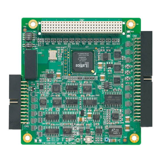
PCM-3810I
PCI-104 12-bit Multifunction Module
Packing List
Before installation, please make sure that you have:
• PCM-3810I Module
• Driver CD
• Startup Manual
If anything is missing or damaged, contact your
distributor or sales representative immediately.
User Manual
For more detailed information on this product,
please refer to the PCM-3810I User Manual on the
CD-ROM (PDF format).
Documents\Hardware Manuals\PCM\PCM-3810I
Declaration of Conformity
FCC Class A
This equipment has been tested and found to comply with
the limits for a Class A digital device, pursuant to part 15 of
the FCC Rules. These limits are designed to provide reason-
able protection against harmful interference when the
equipment is operated in a commercial environment. This
equipment generates, uses, and can radiate radio frequency
energy and, if not installed and used in accordance with the
instruction manual, may cause harmful interference to radio
communications. Operation of this equipment in a residen-
tial area is likely to cause interference in which case the
user is required to correct interference at his own expense.
CE
This product has passed the CE test for environmental spec-
ifications when shielded cables are used for external wiring.
We recommend the use of shielded cables. This kind of
cable is available from Advantech. Please contact your local
supplier for ordering information.
Overview
PCM-3810I is a multifunction module for PCI-104 bus.
Their advanced circuit design provides higher quality and
more functions, including 12-bit A/D conversion, D/A con-
version, digital input, digital output, and counter/timer.
Notes
For more information on this and other Advantech
products, please visit our websites at:
http://www.advantech.com/eAutomation
For technical support and service:
http://www.advantech.com/support/
This startup manual is for PCM-3810I.
Part No. 2003381010
1
Startup Manual
Specifications
Analog Input
Channels
Resolution
FIFO Size
Max. Sampling Rate
Input Range and Gain
List
Drift
Input Impedance
Accuracy
Analog Output
Channels
Resolution
Output Range
Accuracy
Driving Capability 10 mA
Update Rate
Output Impedance 0.1 ohm max.
Non-Isolated Digital Input/Output
Input Channels
Input Voltage
Output Channels 16 (shared)
Output Voltage
1st Edition
March 2010
16 S/E or 8 DIFF or combination
12 bits
4k samples
250 kS/s
Gain
0.5
1
Unipolar
-
0~10 0~5
Bipolar
±10 ±5
Gain
4
Unipolar
0~2.5
Bipolar
±1.25
Gain
All Gain
Zero
15 ppm/°C
Span
25 ppm/°C
300 M / 5pF
INLE: ±1 LSB
DNLE: ±1 LSB
Gain
0.5
1
Gain Error
0.1
0.1
(% FSR)
Gain
4
Gain Error
0.2
(% FSR)
2
12 bits
±
Using Internal
0~5, 0~10,
5,
Reference
Using External
0~+x V @ +x V
≤ x ≤
Reference
(-10
10)
-x~+x V @ +x V
≤
≤
(-10
x
10)
Relative
±1 LSB
Differential
±1 LSB (monotonic)
Non-linearity
Static update
16 (shared)
Low
0.8 V max.
High
2.4 V min.
Low
0.8 V max.
High
2.4 V min.
2
±2.5
8
0~1.25
±0.625
2
0.2
8
0.4
±
10 V
Advertisement
Table of Contents

Related Manuals for Advantech PCM-3810I


Summary of Contents for Advantech PCM-3810I
- Page 1 ±2.5 List Gain Unipolar 0~2.5 0~1.25 For more detailed information on this product, Bipolar ±1.25 ±0.625 please refer to the PCM-3810I User Manual on the Gain All Gain CD-ROM (PDF format). Drift Zero 15 ppm/°C Span 25 ppm/°C Documents\Hardware Manuals\PCM\PCM-3810I...
- Page 2 Board ID ID3 Hardware Installation After the device driver installation is completed, you can now go on to install the PCM-3810I module on your computer. * Default setting is 0 Please follow the steps below to install the module on your system: 1.
- Page 3 Pin Assignments Signal Name Reference Direction Description AI<0…15> AGND Input Analog Input Channels 0 to 15. AGND Analog Ground. ANA TRIG AGND Input Analog threshold Trig- ger. AI DIG TRIG DGND Input Analog Input Digital Trigger. AI PAUSE DGND Input Analog Input Pause GATE GATE.
- Page 4 Analog Input - External Trigger Source Connection Single-ended Channel Connections In addition to pacer triggering, PCM-3810I also allows The single-ended input configuration has only one sig- external triggering for A/D conversions. A low-to-high nal wire for each channel, and the measured voltage edge coming from TRIG will trigger an A/D conversion (Vm) is the voltage referring to the common ground.
Need help?
Do you have a question about the PCM-3810I and is the answer not in the manual?
Questions and answers