Table of Contents
Advertisement
Quick Links
INSTALLATION AND MAINTENANCE INSTRUCTIONS
B112LPA Plug-in Detector Base
For use with the following smoke detectors:
1151A Ionization
2151A Photoelectronic
Specifications
Base Diameter:
Base Height:
Weight:
Mounting:
Operating Temperature Range:
Operating Humidity Range:
Electrical Ratings - includes base and detector
System Voltage:
Maximum Ripple Voltage:
Start-Up Capacitance:
Standby Ratings:
Alarm Ratings:
Reset Voltage:
Reset Time:
Start-up Time:
Relay Contact Ratings:
Resistive or Inductive (60% Power Factor)
Form A:
Form C:
Before Installing
Please thoroughly read the System Sensor manual I56-
407, Guide for Proper Use of System Smoke Detectors,
which provides detailed information on detector spacing,
placement, zoning, wiring, and special applications. Cop-
ies of this manual are available at no charge from System
Sensor. Please also refer to CAN/ULC-S524, Standard for
the Installation of Fire Alarm Systems and CEC Part 1,
Sec. 32.
NOTICE: This manual should be left with the owner/user
of this equipment.
IMPORTANT: The detector used with this base must
be tested and maintained regularly following ULC re-
quirements. The detector used with this base should be
cleaned at least once a year.
D150-03-00
REV: 001
6.2 inches (157 mm)
0.95 inches (24 mm)
0.3 lb. (137 g)
4-inch square box with or without plaster ring. Min. depth–1.5 inches
3-1/2-inch octagon box. Min. depth–1.5 inches
0° to 49°C (32° to 120°F)
10% to 93% Relative Humidity, Noncondensing
24 VDC
4 Volts peak-to-peak
0.02µF Maximum
20 VDC Minimum
29 VDC Maximum
120 µA Maximum
17 mA Minimum
36 mA Maximum
1.4 VDC Minimum
0.3 Seconds Maximum
(The optional RA400ZA operates within specified detector alarm currents.)
34.0 Seconds Maximum
2.0 A @ 30 VAC/DC
2.0 A @ 30 VAC/DC
0.6 A @ 110 VDC
1.0 A @ 125 VAC
1
General Description
The Model B112LPA detector base is designed for use with
System Sensor model 2151A photoelectronic and 1151A
ionization detector heads. This four-wire base is equipped
with screw terminals for the connection of power, ground,
and an optional remote annunciator.
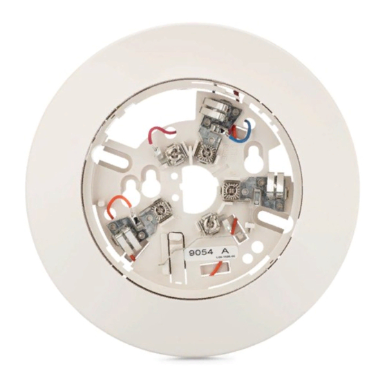
Mounting
The detector base mounts directly to 3-1/2 inch and 4-inch
octagon boxes and 4-inch square boxes, with or without
plaster rings. To mount the base, remove the decorative
ring by rotating it in either direction to unhook the snaps
before separating the ring from the base. Use the screws
supplied with the junction box to attach the base to the box
through the appropriate slots in the base (see Figure 1).
Position the decorative ring around the base and rotate it
in either direction until the ring snaps into place.
I56-1030-000
Advertisement
Table of Contents

Related Manuals for System Sensor B112LPA


Summary of Contents for System Sensor B112LPA
- Page 1 Before Installing General Description Please thoroughly read the System Sensor manual I56- The Model B112LPA detector base is designed for use with 407, Guide for Proper Use of System Smoke Detectors, System Sensor model 2151A photoelectronic and 1151A which provides detailed information on detector spacing, ionization detector heads.
- Page 2 Therefore, before beginning SNAP ON installation, refer to the control panel manufacturer’s loop DECORATIVE RING resistance specification to ensure that it is listed as com- patible with the System Sensor base and smoke detector being installed. SCREWS (NOT SUPPLIED) SHORTING All wiring must be installed in compliance with the Ca-...
- Page 3 NOTE: Schematic Shown for ALARM RELAY ALARM RELAY Reference AUXILIARY CONTACTS (2.8 VDC) AUXILIARY CONTACTS (2.8 VDC) (—) N.O. N.C. (—) N.O. N.C. REMOTE REMOTE ANNUNCIATOR ANNUNCIATOR ALARM ALARM EOL RELAY OUTPUT OUTPUT RELAY RELAY (+IN) 2 3 (+OUT) (+IN) 2 3 (+OUT) DETECTOR POWER LOOP...
- Page 4 Three-Year Limited Warranty System Sensor warrants its enclosed base to be free from defects in #__________, 6581 Kitimat Rd., Unit #6, Mississauga, Ontario, L5N 3T5. materials and workmanship under normal use and service for a period Please include a note describing the malfunction and suspected cause of three years from date of manufacture.
Need help?
Do you have a question about the B112LPA and is the answer not in the manual?
Questions and answers