Table of Contents
Advertisement
Quick Links
Installation AND MAINTENANCE INSTRUCTIONS
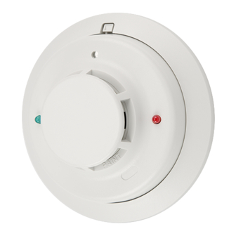
2112/24AITR
Photoelectronic Smoke Detector with
Fixed Heat and Integral Temp-3 Sounder
Figure 1. Wiring diagram for the 2112/24AITR detector:
As with all sounder models, polarity must be observed on the power connections.
+
POWER
TO
DETECTORS
–
UL LISTED
COMPATIBLE
CONTROL
(OPTIONAL)
PANEL
RELEASING
DEVICE
INITIATING
LOOP
Specifications
Diameter:
Height (including mounting bracket):
Weight:
Operating Temperature Range:
Operating Humidity Range:
Latching Alarm:
Audible Signal:
Heat Sensor:
Electrical Ratings
System Voltage (nominal):
Minimum:
Maximum:
Maximum Ripple Voltage:
Standby Current:
Alarm Current:
Reset Voltage:
Reset Time:
Start-up Time:
EOL Relay:
Alarm Initiation and Auxiliary Relay:
Contact Ratings, Resistive Load:
Special Considerations:
Before Installing
Please thoroughly read the System Sensor manual I56-407, Guide for
Proper Use of System Smoke Detectors, which provides detailed informa-
tion on detector spacing, placement, zoning, wiring, and special applica-
tions. Copies of this manual are available at no charge from System
Sensor.
D200-85-00
IMPORTANT: OBSERVE POLARITY
+
P
W
+
R
–
A
ALARM
CONTACT
A
NC
NC
A
(OPTIONAL)
COMMON
C
U
RELEASING
NO
X
NO
5.5 inches (140 mm)
2.05 inches (52 mm)
7.5 oz. (210 g)
32° to 100°F (0° to 38°C)
10% to 93% Relative Humidity, Noncondensing
Reset by momentary power interruption
85 dBA minimum when in alarm or with supply polarity reversed
135°F Fixed Temperature Electronic Thermistor
12 or 24 VDC
10 VDC
35 VDC
30% of nom. Voltage (peak to peak)
50 µA maximum
49 mA typical, 60 mA max. at 12V
57 mA typical, 65 mA max. at 24V
0.8 VDC minimum
1.0 second maximum
30 seconds maximum (after 60 sec. reset)
A77-716B, 12/24 VDC
Note: Relay changes only when the thermal alarm state is reached
1A @ 30 VAC
1A @ 30 VDC
Due to the built-in temporal pattern, use these detectors only with a non-coded power supply.
firealarmresources.com
+
+
–
A
A
NC
NC
COMMON
C
NO
DEVICE
NO
OPTIONAL CLASS A WIRING
NOTICE: This manual shall be left with the owner/user of this equipment.
IMPORTANT: This detector must be tested and maintained following
NFPA 72 requirements. The detector should be cleaned at least once a
year.
1
3825 Ohio Avenue, St. Charles, Illinois 60174
1-800-SENSOR2, FAX: 630-377-6495
EOL POWER
SUPERVISION
RELAY (SHOWN
ENERGIZED)
P
A77-716 12/24V
W
R
ALARM
CONTACT
EOL RESISTOR
A
SPECIFIED BY
U
PANEL
MANUFACTURER
X
A78-2336-16
I56-1241-03R
Advertisement
Table of Contents

Related Manuals for System Sensor 2112


Summary of Contents for System Sensor 2112
- Page 1 Due to the built-in temporal pattern, use these detectors only with a non-coded power supply. Before Installing Please thoroughly read the System Sensor manual I56-407, Guide for NOTICE: This manual shall be left with the owner/user of this equipment. Proper Use of System Smoke Detectors, which provides detailed informa-...
- Page 2 SMOKE DETECTORS FOR MORE PROTECTION AND REQUIRED IN NEW CONSTRUCTION A78-2563-03 Mounting Each 2112/24AITR detector is supplied with a mounting bracket that per- Figure 2: Recommended smoke detector protection for single- mits the detector to be mounted: floor residence with more than one sleeping area: 1.
- Page 3 Dust covers are an effective way to limit the entry of dust into smoke detector sensing chambers. However, they may not completely prevent air- borne dust particles from entering the detector. Therefore, System Sensor Where Smoke Detectors Should NOT Be Installed recommends the removal of detectors before beginning construction or •...
- Page 4 Please include a note describing the malfunction and suspected cause of period of three years from date of manufacture. System Sensor makes no failure. The Company shall not be obligated to repair or replace units other express warranty for this smoke detector.
Need help?
Do you have a question about the 2112 and is the answer not in the manual?
Questions and answers