Table of Contents
Advertisement
Quick Links
INSTALLATION AND MAINTENANCE INSTRUCTIONS
Series
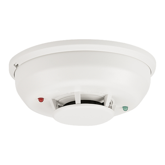
Photoelectric Smoke Detector
2-Wire:
2WTR-B (Form C Relay), 2WTA-B (Sounder)
4-Wire:
4WTR-B (Form C Relay), 4WTA-B (Sounder)
4WTAR-B (Form C Relay, Sounder), 4WITAR-B (Isolated Thermal, Form C Relay, Sounder)
Before Installing
Please read thoroughly System Sensor Applications Guide for System
Smoke Detectors, which provides detailed information on detector spac-
ing, placement, zoning, wiring, and special applications. Copies are avail-
able on System Sensor's web site: www.systemsensor.com.
NOTICE: This manual shall be left with the owner/user of this equipment.
IMPORTANT: This detector must be tested and maintained regularly
following National Fire Protection Association (NFPA) 72 National
Fire Alarm Code requirements. At a minimum, cleaning should be per-
formed annually.
General Description
Models 2WTR-B and 2WTA-B are 2-wire photoelectric smoke detectors;
models 4WTR-B, 4WTA-B, 4WTAR-B, and 4WITAR-B are 4-wire photo-
electric smoke detectors. All models incorporate a state-of-the-art optical
sensing chamber and an advanced microprocessor. The microprocessor
allows the detector to automatically adjust its sensitivity back to the fac-
tory setting when it becomes more sensitive due to contaminants settling
in its chamber. In order for this feature to work properly, the chamber
must never be opened while power is applied to the smoke detector. This
includes cleaning, maintenance or screen replacement. All models also
feature a restorable, built-in, fixed temperature (135°F) thermal detector
and are also capable of sensing a freeze condition if the temperature is
below 41°F.
Models 2WTA-B, 4WTA-B, 4WTAR-B, and 4WITAR-B contain a piezoelec-
tric horn which generates the ANSI S3.41 temporal pattern in an alarm
condition. All detectors on a zone will sound when the power supply to
them is reversed. The RRS-MOD can be used for the power supply reversal
function. The RRS-MOD also enables all the detectors' sounders on a zone
to be synchronized and allows the zone to be silenced from the panel by
entering the alarm silence key at the keypad.
The detector that initiated the alarm condition will have its red LED and
Form C relays (if applicable) latched until reset by panel.
The model 4WITAR-B photoelectronic smoke sensor is isolated from the
fixed-temperature heat sensor, providing a self-resetting, local audible
smoke alarm that does not alarm at the panel. Only the fixed-temperature
heat sensor will cause the 4WITAR-B to initiate an alarm at the panel and
the relay to change its state.
NOTE: In order for all i
3
sounder detectors on a loop to sound when the
panel alarms, the supply voltage polarity must be reversed. A reversing
relay, System Sensor model number RRS-MOD, must be used. The RRS-
MOD is designed to allow all i
3
Series detectors in the same loop to sound
when one of the detectors goes into alarm. In addition, the RRS-MOD will
synchronize all of the i
3
Series sounder smoke detectors on the loop. Some
panels may require the use of programmable outputs. Refer to System Sen-
sor literature for further information on the RRS-MOD.
All i
3
Series detectors are designed to provide open area protection. Two-wire
models must be used with compatible UL Listed panels only.
When used with an "i
3
Ready" control panel or the i
module (refer to installation manual), the 2WTR-B and 2WTA-B are ca-
pable of generating a "maintenance needed" signal. The 2W-MOD2 can
indicate a need for cleaning, replacement, or a freeze trouble at the control
panel or module.
The 2W-MOD2 has replaced the previous model number 2W-MOD. To en-
sure proper remote maintenance signaling capabilities, do not use the 2W-
MOD with i
3
model numbers 2WTR-B and 2WTA-B.
D100-99-00
3
Series 2W-MOD2
WARNING
Installation of the 2WTR-B, 2WTA-B, 4WTR-B, 4WTA-B, 4WTAR-B, and
4WITAR-B detectors is simplified by the use of a mounting base that may
be pre-wired to the system, allowing the detector to be easily installed
or removed. The mounting base installation is further simplified by the
incorporation of features compatible with drywall fasteners.
Two LEDs on the detector provide a local visual indication of the detec-
tor's status:
Table 1: Detector LED Modes
Green LED
Power-up
Blink 10 sec
Normal (standby)
Blink 5 sec
Out of sensitivity
—
Freeze Trouble
—
Alarm
—
During an initial power-up delay, the red and green LEDs will blink syn-
chronously once every ten seconds. It will take approximately 80 seconds
for the detector to finish the power-up cycle (see Table 2).
Table 2: Power-up Sequence for LED Status Indication*
Condition
Initial LED Status Indication
Initial LED Status Indication
(if excessive electrical noise is present)
* R efer to Electrical Specifications for start-up time in conjunction with
panel alarm verification.
NOTE: If, during power-up, the detector determines there is excessive
electrical noise in the system such as those caused by improper ground-
ing of the system or the conduit, both LEDs will blink for up to 4 minutes
before displaying detector status (see Table 2).
After power-up has completed and the detector is functioning normally
within its listed sensitivity range, the green LED blinks once every five
seconds. If the detector is in need of maintenance because its sensitivity
has shifted outside the listed limits, the red LED blinks once every five
seconds. When the detector is in the alarm mode, the red LED latches on.
The LED indication must not be used in lieu of the tests specified under
Testing. In a freeze trouble condition, the red LED will blink once every 10
seconds (refer to Table 1).
To measure the detector's sensitivity, the i
red Sensitivity Reader tool (see Figure 4) should be used. Refer to instruc-
tions manual D100-98-00 for the proper use of the SENS-RDR.
Models 2WTR-B and 2WTA-B also include an output that allows an op-
tional Model RA400Z Remote Annunciator to be connected.
Mounting
General spacing guidelines are 30˝×30˝, with each detector covering 900
ft
2
under maximum conditions.
Consult NFPA 72, the local Authority Having Jurisdiction (AHJ), and/or
applicable codes for specific information regarding the spacing and place-
ment of smoke detectors.
Each i
3
Series detector is supplied with a mounting base that can be ceil-
ing- or wall-mounted:
1. To a single gang box, or
2. To a 3
1
⁄
-inch or 4-inch octagonal box, or
2
3. To a 4-inch square box with a plaster ring, or
4. Direct mount or to ceiling using drywall fasteners.
1
3825 Ohio Avenue, St. Charles, Illinois 60174
1-800-SENSOR2, FAX: 630-377-6495
www.systemsensor.com
Red LED
Blink 10 sec
—
Blink 5 sec
Blink 10 sec
Solid
Duration
80 seconds
4 minutes
3
Series Model SENS-RDR Infra-
I56-2170-007R
Advertisement
Table of Contents

Related Manuals for System Sensor 2WTR-B


Summary of Contents for System Sensor 2WTR-B
-
Page 1: General Description
A reversing To measure the detector’s sensitivity, the i Series Model SENS-RDR Infra- relay, System Sensor model number RRS-MOD, must be used. The RRS- red Sensitivity Reader tool (see Figure 4) should be used. Refer to instruc- MOD is designed to allow all i Series detectors in the same loop to sound tions manual D100-98-00 for the proper use of the SENS-RDR. when one of the detectors goes into alarm. In addition, the RRS-MOD will Models 2WTR-B and 2WTA-B also include an output that allows an op- synchronize all of the i Series sounder smoke detectors on the loop. Some tional Model RA400Z Remote Annunciator to be connected. panels may require the use of programmable outputs. Refer to System Sen- sor literature for further information on the RRS-MOD. Mounting All i Series detectors are designed to provide open area protection. Two-wire General spacing guidelines are 30˝×30˝, with each detector covering 900 models must be used with compatible UL Listed panels only. -
Page 2: Wiring Installation Guidelines
PANEL 2WTA-B MODEL Tamper-Resistant Feature S0122-00 NOTE: FOR ALL COMPATIBLE ADEMCO PANELS, The i Series detectors include a tamper-resistant feature that prevents re- DO NOT EXCEED 30 OHMS LINE IMPEDANCE. moval from the mounting base without the use of a tool. To engage the NOTE: ONLY ONE 2WTR-B DETECTOR PER ZONE CAN BE USED. tamper-resistant feature, cut the small plastic tab located on the mount- ing base (Figure 2), and then install the detector. To remove the detector from the base once it has been made tamper resistant, use a small screw- NOTE: Only one 2WTA-B detector shall be installed on a zone, unless the driver to depress the square tamper release tab, located on the skirt of the panel switches the zone to a reverse polarity, non-current limited power mounting base, and turn the detector counterclockwise. supply. For panels that do not provide this feature, a reversing relay, Sys- tem Sensor model RRS-MOD, may be used. When utilized with the 2WTA-... - Page 3 Therefore, System Sensor recommends the removal of detectors checked and it should be cleaned as outlined in the Maintenance section. before beginning construction or other dust producing activity. When re- If the detector still fails, it should be replaced. turning the system to service, be sure to remove the dust covers from any Notify the proper authorities when the system is back in service. detectors that were left in place during construction. Loop Verification (models 2WTR-B and 2WTA-B only) CAUTION Loop verification is provided by the EZ Walk loop test feature. This feature Smoke detectors are not to be used with detector guards unless the combi- is for use with i Series compatible control panels or the i Series 2W- MOD2 module only. The EZ Walk loop test verifies the initiating loop wir- nation has been evaluated and found suitable for that purpose.
- Page 4 2-wire 4-wire System Voltage –Nominal: 12/24 12/24 Reset Time (min): seconds (Non-polarized for Max. Start-up Capacitance: — µF 2WTR-B and 4WTR-B) Max. Initial Start-up Time: seconds Min.: Alarm Verification** Max.: Start-up Time: seconds Max. Ripple Voltage: % peak to peak * Direct Power (Non-reverse Polarity): 130 mA limited by panel.
Need help?
Do you have a question about the 2WTR-B and is the answer not in the manual?
Questions and answers