
Related Manuals for CIS VCC-2CXP6M


Summary of Contents for CIS VCC-2CXP6M
- Page 1 Rev.905-0186-02 CoaXPress I/F 2M CMOS B/W Camera VCC-2CXP6M Product Specifications & Operational Manual CIS Corporation ©2019 CIS Corporation. All rights reserved.
-
Page 2: Table Of Contents
Image Quality Selection Mode ........................22 5.21. Defective Pixels Correction ........................22 5.22. Test Pattern Indication ..........................26 5.23. Cursor Indication ............................ 26 5.24. LED Operational Mode ..........................26 5.25. Camera Timing Output ..........................26 ©2019 CIS Corporation. All rights reserved. - Page 3 Dimensions ............................... 29 7.1. Camera Dimensions ..........................29 7.2. Optical Axis Accuracy ..........................30 Case for Indemnity ............................31 8.1. Product Warranty ............................ 31 8.2. CMOS Pixel Defect........................... 31 8.3. Product Support ............................31 ©2019 CIS Corporation. All rights reserved.
-
Page 4: Handling Precautions
1.3. Disclaimers (Exception Clause) CIS shall be exempted from taking responsibility and held harmless for damages or losses incurred by the following cases. □ In case damages or losses are caused by earthquake, lightning strike, fire, flood, or other acts of God. -
Page 5: Product Outline
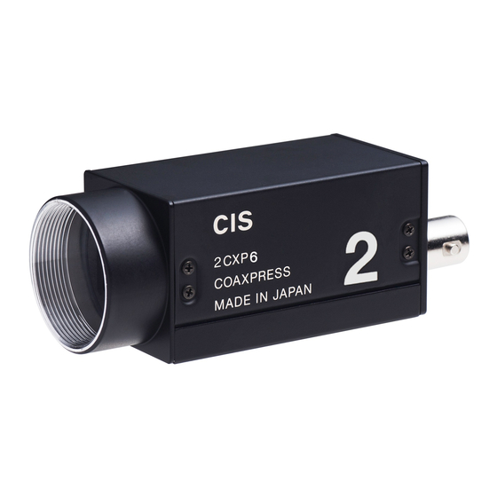
VCC-2CXP6M Rev.905-0186-02 Product Outline VCC-2CXP6M is a CoaXPress interfaced and 2M resolution camera module. 1/1.7 type B/W CMOS sensor is utilized. 2.1. Features □ Small footprint: 29mm(H) x 29mm(W) x 55mm(D) □ Global shutter type CMOS sensor □ CoaXPress CXP-3, CXP-6 are supported. -
Page 6: Specifications
Vertical 8 areas can be set. Power requirements PoCXP: 18.5~26V Power consumption 3.4W(CXP-3), 3.6W (CXP-6), [At free run] Mechanical Specifications Dimensions H:29mm W:29mm D:55mm (Without protruding portion) Weight Approx. 66g Lens mount C mount ©2019 CIS Corporation. All rights reserved. -
Page 7: Camera Input And Output Signals Specifications
SN74AHCT1G14 (Equlvalent) 3.2.2 6pins Circular Connector No.3 pin: SIGNAL_OUT Circuit □ 5.0V CMOS logic level output □ Output voltage Low: 0.35Vdc (Max), High: 4.5Vdc (Min) +5.0V Camera Internal Circuit カメラ内部回路 (CAMERA_INTERNAL) SIGNAL_OUT SN74LV1T32 (Equlvalent) ©2019 CIS Corporation. All rights reserved. -
Page 8: External Connector Pin Assignment
3.3.1 6pins Circular Connector HR10-10R-12PA(73) (Hirose) or equivalent HR10A-7R-6PB (Hirose) or equivalent Pin No. Signals Description SIGNAL_OUT Exposure/FVAL/LVAL/LinkTrigger TRIGGER_IN Trigger input Conduction with camera module ※NC=Non-Connection. Do not connect anything to the terminal. 3.3.2 75Ω BNC Connector (BCJ-BPLHA Canare) ©2019 CIS Corporation. All rights reserved. -
Page 9: Led Indicator
※ The LED blinks by 12.5Hz when TriggerMode is Off. When TriggerMode is On, LED blinks by the trigger cycle. (It may appear as lighted status, not blinked status at fast trigger.) 3.4. Spectral Response ※ The lens characteristics, IR cut filter characteristics, and the illuminant characteristics are excluded. ©2019 CIS Corporation. All rights reserved. -
Page 10: Output Timing
Video output Effective 1H total Time Link rate H blank data pixel numbers 1H[us] format CXP-3 Mono8 6.36 Mono10 7.81 Mono12 9.21 CXP-6 Mono8 3.18 Mono10 3.91 Mono12 4.61 Sensor Operation clk 74.25 MHz ©2019 CIS Corporation. All rights reserved. -
Page 11: Vertical Sync. Timing
1316 6.36 8.37 Mono10 1248 1316 7.81 10.28 Mono12 1248 1312 9.21 12.08 CXP-6 Mono8 1248 1316 3.18 4.18 Mono10 1248 1316 3.91 5.15 Mono12 1248 1312 4.61 6.05 Sensor Operation clk 74.25 MHz ©2019 CIS Corporation. All rights reserved. -
Page 12: Camera Function
UserSetSave >Excute 5.3. Link Speed and Link Count Transfer Control CXP3_X1 ConnectionConfig CXP6_X1 CXP-3: Link speed=3.125Gbps, Link count=1 CXP-6: Link speed=6.250Gbps, Link count=1 ※Please do not change ConnectionConfig while grabbing (acquiring image). ©2019 CIS Corporation. All rights reserved. -
Page 13: Pixel Format
: Trigger mode On : Validate the trigger selected by TriggerSource. (TriggerSelector = FrameStart) Off : Invalidate the trigger selected by TriggerSource. (TriggerSelector = AcquisitionStart) ※Please do not change TriggerMode while grabbing (acquiring image). ©2019 CIS Corporation. All rights reserved. - Page 14 A trigger is generated in the camera and capture images for 1 frame when this command is executed. Please make sure to set TriggerSource to Software. OFF (Free RUN) TriggerMode = Timeed (AcquisitionStart) (TriggerSelector) LineSync TriggerSyncMode TriggerActivation (FrameStart) ClockSync ・RisingEdge(Timed) TriggerSource ・FallingEdge(Timed) ・LinkTrigger0 ・LevelHigh(TriggerWidth) ・Line0 ・LevelLow(TriggerWidth) ・TriggerSoftware >Excute ©2019 CIS Corporation. All rights reserved.
-
Page 15: Trigger Sync. Mode And Delay Time To Start Exposure
※Since overlapping operation is invalid at CLK sync. mode, the trigger at this timing shall be masked and “IllegalTriggerFlag” will not become “1”. Device Control ErrorFlagReset Execute This is to reset IllegalTriggerFlag to “0”. ©2019 CIS Corporation. All rights reserved. -
Page 16: Fixed Trigger Shutter Mode (Linesync) H Sync. Trigger
□ Trigger input while exposure period (Exposure Time) shall be ignored in the camera. ((A) in the drawing below) Please note that a trigger shorter than 1 frame cycle shall not be used. ©2019 CIS Corporation. All rights reserved. -
Page 17: Fast Fixed Trigger Shutter Mode (Clocksync) Clk Sync. Trigger
The next trigger while outputting video for the prior trigger cannot be accepted. □ Trigger input while exposure period and reading out period shall be ignored in the camera. (Refer to (A) and (B) in the drawing next page.) ©2019 CIS Corporation. All rights reserved. -
Page 18: Pulse Width Trigger Shutter Mode (Linesync) H Sync. Trigger
Functionally, there is no upper limitation, but noises such as dark noises shadings may be noticeable at long time exposure. There is an exposure time period for approx. 4.997µs at the edge right after exposure time. □ SP OUT (Exposure Out) Approx. 4.997us Actual exposure period ©2019 CIS Corporation. All rights reserved. -
Page 19: Fast Pulse Width Trigger Shutter Mode (Clocksync) Clk Sync. Trigger
Functionally, there is no upper limitation, but noises such as dark noises shadings may be noticeable at long time exposure. □ There is an exposure time period for approx. 4.997μs at the edge right after exposure output. SP OUT (Exposure Out) Approx. 4.997us Actual exposure period ©2019 CIS Corporation. All rights reserved. -
Page 20: Exposure Time
※ The maximum of H sync. trigger mode (LineSync) shall be clipped with effective line count (Including at partial). ※ CLK sync. trigger mode (ClockSync) can be set from CLK 10us~200ms. It shall not be clipped with effective line count. ©2019 CIS Corporation. All rights reserved. -
Page 21: Formula To Calculate Manual Shutter Values With H Sync. Mode
(Approx. 20ms: Command ACK is the rough standard.) at continuous operation mode. In case the gamma coefficient is changed while waiting trigger to be input, the gamma updated image shall be output with the trigger after the completion of rewriting the table. ©2019 CIS Corporation. All rights reserved. -
Page 22: Partial Scan (Roi)
・Height: ※Please make sure that the Height setting does not overlap with other Regions correspond to OffsetY setting. This is to set the Offset settings for X direction of the Region. This model VCC-2CXP6M is ・OffsetX: fixed to 0. This is to set the Offset settings for Y direction of the Region. - Page 23 Partial effective line 1 + Partial effective lines 2 + ・・・ + Partial effective lines 8 Please note that sum total of partial effective line numbers from 1~8 (except V blanking lines) has to be less than 1248. V blanking lines at partial mode is 64 or 68H. ©2019 CIS Corporation. All rights reserved.
-
Page 24: 2×2 Binning Mode
□ This mode cannot be used with partial scan (ROI) function. Frame rate at Bining mode [fps] 2x2Bining mode PixelFormat Link rate (fps) (Number of pixels) CXP6_X1 CXP3_X1 (816x624) Mono8 796.1 398.0 Mono10 662.3 331.1 Mono12 521.8 260.9 ©2019 CIS Corporation. All rights reserved. -
Page 25: Black Level Adjustment
Data increased after shipment or the one registered by users. These data can be entirely erased anytime by DefectPixelDefault. The number of data registerable by users is 128 points. (Note: Up to 32 points per CH.) □ ©2019 CIS Corporation. All rights reserved. - Page 26 In case the coordinate same as the defective data at ex-factory is specified, it shall be ignored. Only the added pixels by “Defective pixels detection registered by user” or “Defective pixels added by user” can be deleted. Data at ex-factory cannot be deleted by this command. ©2019 CIS Corporation. All rights reserved.
- Page 27 When detecting defects, partial scan, binning mode, and shading shall be OFF. (Size shall be set to 1632 x 1248) When changing the threshold value of DefectDetectionThresholdValue and acquiring the defective pixels correction data, please execute DefectPixelDefault and delete the defective pixels correction data registered by user to reacquire it. ©2019 CIS Corporation. All rights reserved.
- Page 28 DefectPixelChannelCount: This is to indicate the number of defects of channel number specified at ChannelNumber. The specified number of the defect of the channel number is the sum total of the defects at ex-factory and the number of defects registered by user. ©2019 CIS Corporation. All rights reserved.
-
Page 29: Test Pattern Indication
: This is to indicate effective period of frame by Hi Active. LineActive : This is to indicate effective period of line by Hi Active. TriggerPacketActive : This is to output uplink trigger packet signal from frame grabber by decoding. ©2019 CIS Corporation. All rights reserved. -
Page 30: User Id Save
Temperature Indication □ This is to indicate the temperature of the image sensor. (Indicate by ℃) DeviceControl DeviceTemperature ReadOnly [Note] This value shall not be calibrated. Please regard this value as a reference value ©2019 CIS Corporation. All rights reserved. -
Page 31: Factory Settings
This is to specify the position of cursor Y CursorColor White Cursor color White/Black BiningHorizontal 2x2 binning mode BiningVertical 2x2 binning mode DeviceIndicatorMode Active Indicate LED indicator LineSource Circular 6P-3pin output settings DeviceUserID User letter string setting (16 letters) ©2019 CIS Corporation. All rights reserved. -
Page 32: Dimensions
VCC-2CXP6M Rev.905-0186-02 Dimensions 7.1. Camera Dimensions ©2019 CIS Corporation. All rights reserved. -
Page 33: Optical Axis Accuracy
VCC-2CXP6M Rev.905-0186-02 7.2. Optical Axis Accuracy ©2019 CIS Corporation. All rights reserved. -
Page 34: Case For Indemnity
If you use the product properly and discover a defect during the warranty period, and if that was caused by designing or manufacturing, CIS Corporation, at its option, repairs or replaces it at no charge to you. Products out of warranty period will be subject to charge.
Need help?
Do you have a question about the VCC-2CXP6M and is the answer not in the manual?
Questions and answers