Advertisement
Quick Links
LED TUNABLE TROFFER
STR-22-25W-CCT / STR-24-40W-CCT
FCC WARNING:
WARNING:
Changes or modifications to this unit not expressly approved by the
party responsible for compliance could void the user authority to operate the
equipment.
NOTES:
This equipment has been tested and found to comply with the limits
for a Class B digital device, pursuant to Part 15 of the FCC Rules. These limits
are designed to provide reasonable protection against harmful interference in
a residential installation. This equipment generates, uses and can radiate radio
frequency energy and, if not installed and used in accordance with the instructions,
may cause harmful interference to radio communications.
However, there is no guarantee that interference will not occur in a particular
installation. If this equipment does cause harmful interference to radio or television
reception, which can be determined by turning the equipment off and on, the user
is encouraged to try to correct the interference by one or more of the following
measures:
• Reorient or relocate the receiving antenna.
• Increase the separation between the equipment and receiver.
• Connect the equipment into an outlet on a circuit different from that to which
the receiver is connected.
• Consult the dealer or an experienced radio/TV technician for help.
ASSEMBLY INSTRUCTIONS
• NON-REPLACEABLE LEDS.
• IF YOU ARE NOT FAMILIAR WITH STATE AND LOCAL ELECTRICAL CODES, IT IS
RECOMMENDED THAT YOU CONSULT WITH A QUALIFIED ELECTRICIAN.
• DO NOT USE IN WET LOCATIONS, USE INDOORS ONLY.
•
CAUTION:
LEDS EMIT BRIGHT LIGHT. AVOID LOOKING DIRECTLY INTO THE LIGHT
SOURCE FOR PROLONGED PERIODS TO AVOID EYE DAMAGE.
av
• DIM MABLE WITH O~ 1
DIMMER (SOLD SEPARATELY).
• MULTI-VOLT (100~277 VOLn FOR COMMERCIAL OR RESIDENTIAL USE.
INSTA LL ATI O N
(CAUTION: BEFORE BEGINNING INSTALLATION TURN OFF THE CIRCUIT BREAKER AND LIGHT SWITCH)
1. Make sure the T - b ars have been fixed in the ceiling like the picture show (T-bars are not included).
2. Put the troffer upon the ceiling by leaning to one side, and the lower side of the troffer touches the T-bar.
3. Remove the set screw (Part AA) to open the driver enclosure cover (Part BB) using a screwdriver enclosure.
4. Remove one of the knockouts (Part CC) on the driver (Part EE) by using a screwdriver (Part DD).
5. Connect wires from a power source to the fixture.
NOTE: ALL WIRES PASS THROUGH THE KNOCKOUT
• Connect the HOT wire (black) from the power source to the wiring terminal marked "AC-L"
• Connect the NEUTRAL wire (white) from the power source to the wiring terminal marked· AC-N"
• Connect the GROUND wire (green/yellow) from the power source to the driver house.
To connect a dimmer:
• Connect the PURPLE wire to the wiring terminal marked
• Connect the GREY wire to the wiring terminal marked
6. Close and secure the enclosure cover (Part BB) using the set screw (Part AA).
7. *Optional* Correlated color temperature (CCT).
Turn the switch to the position of 3000K, 4000K or 5000K to select the correlated color
temperature (CCT).
8. Secure the fixture light to T - b ars (grid) and bend all four built-in integral clips (Part FF)
outwards to engage the T-bar.
TROUBLE SHOOTING
PROBLEM
POSSIBLE CAUSE
Light will not
A. Light switch is turned off.
come on
B. Fuse is blown or circuit
breaker is turned off.
C. Incorrect circuit wiring.
www.spitzerlighting.com
INSTALLATION MANUAL
·Turn off electricity at main fuse box (or circuit breaker box) before beginning installation by removing fuse or switching off
circuit breaker.
• Be careful not to damage or cut the wire insulation (covering) during fixture installation. Do not permit wires to contact any
surface having a sharp edge. To do so may damage or cut the wire insulation, which could cause serious injury or death from
electric shock.
• LED electronics can be damaged by electro static discharge (ESD) shock. Before installation, discharge yourself by touching a
grounded bare metal surface to remove this hazard. To avoid damage, do not touch the LED module.
• All electrical connections must be in agreement with local codes, ordinances or the national electric code (NEC).
• Contact your municipal building department to learn about your local codes, permits and/or inspections.
• RISK OF FIRE - most dwellings built before 1985 have supply wire rated for l 40'F/60
installation.
• Do not connect this fixture to an electrical system that does not provide a means for equipment grounding. Never use a fixture
in a two-wire system that is not grounded. If you are not sure your lighting system has a grounding means, do not attempt to
install this fixture. Contact a qualified, licensed electrician for information with regards to proper grounding methods as required
by the local electrical code in your area.
• If a dimmer control switch is used with this fixture, obtain professional advice to determine the correct type and electrical rating
required.
I , BEFORE BEGINNING ASSEMBLY, INSTALLATION OR OPERATION OF PRODUCT, MAKE SURE ALL PARTS ARE PRESENT.
I COMPARE PARTS WITH PACKAGE CONTENTS LIST AND DIAGRAM ON PREVIOUS PAGE. IF ANY PART IS MISSING OR
I DAMAGED, DO NOT ATTEMPT TO ASSEMBLE, INSTALL OR OPERATE THE PRODUCT. CONTACT CUSTOMER SERVICE FOR
I REPLACEMENT PARTS.
I• TOOLS REQUIRED FOR ASSEMBLY (NOT INCLUDED): SCREWDRIVER, PHILLIPS SCREWDRIVER, PLIERS, ELECTRICAL TAPE,
I WIRE CUTTERS, SAFETY GLASSES, LADDER, WIRE STRIPPER.
L ------ - - - - -------- - - - - -------- - - - - ------- J
CAUTI O N: Before attempting to clean the fixture, disconnect the power to the fixture by turning
the breaker off or removing the fuse from the fuse box. This LED light fixture is made from quality
materials that will last many y ears with minimum care and maintenance. You may want to clean
the fixture with a soft cloth periodically. To maintain the best appearance of the fixture, do not
use cleaners with chemicals, solvents or harsh abrasivers. Do not use liquid cleaner on the LEDs,
LED driver, or wiring inside the light fixture.
"DIM+".
"DIM-".
SOLUTION
i � -
A. Turn light switch on.
B. Replace fuse or turn circuit
breaker on.
C. Verify that fixture is wired
properly.
702 Interchange Blvd., Newark, DE 19711 • Toll Free: 844-312-4574
PLEASE READ AND UNDERSTAND THIS ENTIRE MANUAL BEFORE ATTEMPTING TO ASSEMBLE,
OPERATE OR INSTALL THE PRODUCT
PRE-INSTALLATION
CARE AND MAINTENANCE
FF
3000K 4000K 5000K
1·
�J
Iii
...
FF
-�
WARNING
C A U TION :
C.Consult a qualified electrician before
°
[3E]
-
LED DRIVER
AA
-
DD�
✓
;
ct
_;
Specification is subject to change without notice
knockout
L'.
'5
�
"
.
0
C:
-"'
r::
knockout
�
BB
.
�"�
---
Advertisement

Subscribe to Our Youtube Channel
Related Manuals for Spitzer LIGHTING STR-22-25W-CCT


Summary of Contents for Spitzer LIGHTING STR-22-25W-CCT
- Page 1 LED TUNABLE TROFFER STR-22-25W-CCT / STR-24-40W-CCT INSTALLATION MANUAL PLEASE READ AND UNDERSTAND THIS ENTIRE MANUAL BEFORE ATTEMPTING TO ASSEMBLE, OPERATE OR INSTALL THE PRODUCT WARNING ·Turn off electricity at main fuse box (or circuit breaker box) before beginning installation by removing fuse or switching off circuit breaker.
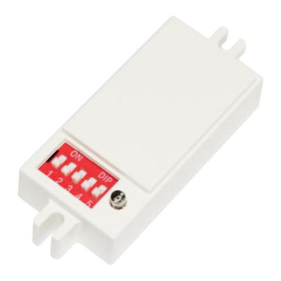
- Page 2 STR-SNSR Color Changeable Troffer Motion Sensor Type: Date: SKU No: ACCESSORY FOR THE COLOR CHANGEABLE TROFFER DESCRIPTION The motion sensor is designed based on the Doppler principle, it transmits the high frequency electromagnetic wave through the antenna and receives the reflected wave. Based on this principle it judges the movement of the object within the coverage range, and control radar motion sensor.
- Page 3 STR-SNSR Color Changeable Troffer Motion Sensor Type: Date: SKU No: ACCESSORY FOR THE COLOR CHANGEABLE TROFFER LEAD WIRE DIAGRAM DIAL SWITCH SETTINGS 1: Distance Setting 2/3: Time Setting 100% 5min 10min According to the different application, the defect distance can be set to 20min 100%, 50% by the dial switch.
Need help?
Do you have a question about the STR-22-25W-CCT and is the answer not in the manual?
Questions and answers