Table of Contents
Advertisement
Quick Links
Advertisement
Table of Contents

Related Manuals for Brink Air Comfort


Summary of Contents for Brink Air Comfort
- Page 1 Installation regulations Air Comfort English...
- Page 3 Children may not play with the appliance. If you need a new power cable, always order the replacement from Brink Climate Systems B.V. To prevent dangerous situations, a damaged mains connection must only...
-
Page 4: Table Of Contents
9.1 Cleaning filter......37 3.1.1 Air Comfort......7 9.2 Maintenance. -
Page 5: Delivery
▪ An indirectly fired air heater type Air Comfort ▪ Occupant's instructions Before the appliance is installed, first check that the Air Comfort has been delivered complete and undamaged. Should anything not be in order, contact Brink Climate Systems B.V. -
Page 6: Use
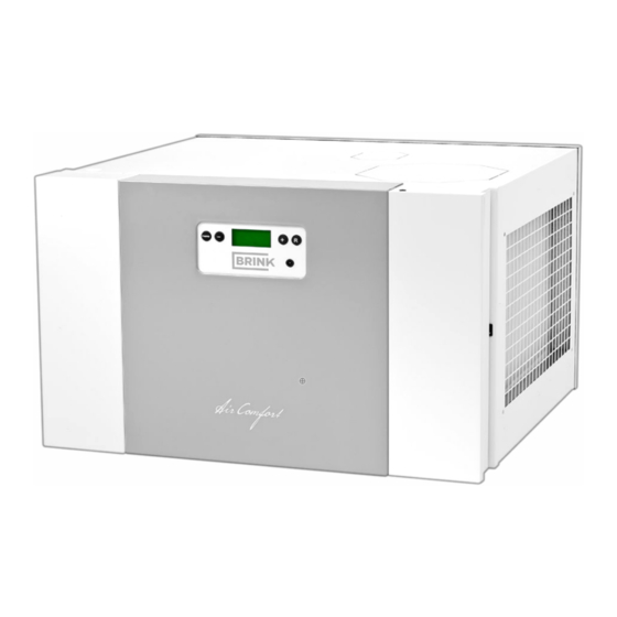
2 Use The Air Comfort appliance is an indirectly fired air heater for domestic use. In order to achieve a perfect interior climate with a constant room temperature, the air flow is automatically adjusted according to the discharge temperature. If required, the appliance can (partially) suck in outside air. -
Page 7: Version
3 Version 3.1 Technical information 3.1.1 Air Comfort Specification Value Supply voltage [V/Hz] 230/50 Dimensions (l x w x h) [mm] 676 x 640 x 429 Weight [kg] Filter class Water connection (Ø) [mm] Water capacity exchanger [l] Water range [°C] 45/35 Air suction temperature [°C]... -
Page 8: Heating Capacity [Kw] At Other Water Temperatures
4.73 4.45 5.71 5.40 5.10 4.79 3.1.4 Cooling Specification Value Water range [°C] 7/11 Air suction temperature [°C] Nominal Maximal Flow rate [m Cooling capacity [kW] 1.49/1.59 1.65/1.75 Water capacity [l/h] Water pressure head [kPa] 3.63 4.32 Air Comfort 614788-B... -
Page 9: Connections And Dimensions
3.2 Connections and dimensions Primary measurements Air Comfort , 0 0 Ø 2 Position of duct connection Air Comfort 614788-B Brink / 9... -
Page 10: Air Comfort Right-Hand Version
3.2.1 Air Comfort right-hand version With a right-hand version of the Air Comfort the discharge opening is located on the right-hand side. Air Comfort right-hand version Position of water connection and condensation discharge connection of the right-hand version Air Comfort 614788-B... -
Page 11: Air Comfort Left - Hand Version
3.2.2 Air Comfort left - hand version With a left-hand version of the Air Comfort the air outlet is located on the left-hand side. The measurements of the right-hand and left-hand versions and the position of the air outlet are identical. -
Page 12: Opened-Up Right-Hand Appliance
Connectors - The connectors are located behind the protective cover and are used as extra control inputs and outputs, for example for the CO sensor, the 4-position switch and the frost protection. Condensation discharge feed-through - When using the appliance in combination with a heat recovery unit. Air Comfort 614788-B... - Page 13 Water connections left-hand version Air Comfort Air Comfort 614788-B Brink / 13...
-
Page 14: Operation
4 Operation 4.1 Description The Air Comfort is an advanced air heater for domestic use. The air is heated using a heat exchanger. Depending on the discharge temperature, the system ventilator will transport on a continuous scale less or more air through the appliance A control unit with a microprocessor regulates and monitors the safe operation of the appliance. - Page 15 4. 1. Air flow [m 2. Temperature [°C] 3. Air flow-cooling [m 4. Air flow-max [m 5. Air flow-min [m 6. Temperature fan out [°C] 7. Temperature start [°C] 8. Temperature max. [°C] Air Comfort 614788-B Brink / 15...
-
Page 16: Fixed Programme
4. Air flow-max [m 5. Air flow-min [m 6. Temperature fan out [°C] 7. Temperature start [°C] 8. Temperature max. [°C] A cooling demand through a closed switch input 'cooling' has priority over any position of the 4-position switch. Air Comfort 614788-B... -
Page 17: Hru Programme
4.2.3 HRU programme If the Air Comfort is used in combination with a heat recovery unit, the control of the system ventilator can be coupled to the heat recovery unit with this HRU programme. The 4-position switch of the heat recovery unit can therefore be used to determine the air flow of the system ventilator in the Air Comfort. - Page 18 A cooling demand through a closed switch input 'cooling' has priority over the position of the 4-position switch of the heat recovery unit. The CO sensors that are connected to the heat recovery unit have no influence on the control of the Air Comfort. Air Comfort 614788-B...
-
Page 19: Co₂-Control
If the CO concentration in a room gets above the minimum setting value, the air flow of the system ventilator of the Air Comfort increases. The air flow varies depending on the measured CO concentration(s). -
Page 20: Frost Protection
(anti- pendulum time). The system ventilator continues to run on the basis of the position of the 4-position switch as long as the time has not been exceeded. Air Comfort 614788-B... -
Page 21: Installation
25). 5.2 Placing the appliance When placing the Air Comfort take into account the following environmental factors: ▪ The room where the appliance is installed must be frost-free. ▪ The room where the appliance is set up must provide enough space for service. There must be at least 1 m of free space at the front and a free standing height of 1.8 m. -
Page 22: Installing Renovent Excellent On Air Comfort
2. Remove the insulation that is released. 3. Stick the 4 black buffers from the siphon set onto the indentation (1) of the top plate of the Air Comfort. 4. Stick the sealing tape of the siphon set over the edge of the break-off opening (3). -
Page 23: Water Connections
2. Remove the insulation that is released. 3. Stick the 4 black buffers from the siphon set onto the indentation (1) of the top plate of the Air Comfort. 4. Stick the sealing tape of the siphon set over the edge of the break-off openings (2, 3). -
Page 24: Connecting Ducts
Renovent Excellent heat recovery unit. 3. Feed the condensation discharge tube through the tulle underneath the control panel. 4. Place the front covers back on the Air Comfort 5.4 Connecting ducts Connect the warm air duct onto the coupling ring of the air outlet: 1. -
Page 25: Electrical Connections
Ensure that the ducts do not form a straight connection between 2 rooms, so that cross-talk interference does not arise. 5.5 Electrical connections The Air Comfort must be connected to the electricity network with the mains plug. See section Electrical connection accessories... -
Page 26: Connecting The Renovent Excellent
5.5.3 Connecting the Renovent Excellent Connect the 2‑pin green eBus connector of the Renovent Excellent heat recovery unit to the 2‑pin green eBus connector of the Air Comfort appliance. Air Comfort 614788-B... -
Page 27: Display
5 seconds in order to activate the background lighting of the display without anything changing in the menu. If the buttons are not pressed for 5 minutes, the display returns automatically to the operating mode. Air Comfort 614788-B Brink / 27... -
Page 28: Operating Mode
The following messages can be shown on the display: Notification message Description FILTER The filter must be cleaned or replaced, see Clean filter (zie Cleaning filter op pagina 37). Fixed programme (op pagina 16) has been set. HRU programme (op pagina 17) has been set. Air Comfort 614788-B... -
Page 29: Setup Menu
(op pagina 47) for an overview of the possible settings. Incorrect settings can disrupt the operation of the appliance. Contact Brink Climate Systems B.V. when the settings, which are not described in these installation instructions, have to be changed. Changing the setting values: 1. -
Page 30: Read Out Menu
2 Press to navigate to the readout menu READ. 5 Press to return to the menu choice. 6 Press again to return to the operating mode. 3 Press [Menu] to activate the readout menu. Air Comfort 614788-B... -
Page 31: Service Menu
6 Press to return to the menu choice. 7 Press again to return to the operating mode. 4. Press to navigate through the error messages in the service menu. Air Comfort 614788-B Brink / 31... -
Page 32: Starting Appliance
(op pagina 29). 7.3 Other settings for fitter Use the Setup menu (op pagina 29) to change the setting values of the appliance. See the Parameter list (op pagina 47) for an overview of the possible settings. Air Comfort 614788-B... -
Page 33: Connecting Several Air Comfort Appliances
7.3.2 Connecting Air Comfort appliance with Renovent Excellent appliance If a Renovent Excellent heat recovery unit is connected to the Air Comfort appliance or a series of a maximum of 4 Air Comfort appliances, then the Renovent Excellent type must be set with parameter 27, see the... -
Page 34: Fault
Check the dipswitches, see diagram Replace the circuit board if the message E999 does not disappear and the dipswitches are in the correct position. Air Comfort 614788-B... -
Page 35: Display Codes
The fault is automatically reset. External fault on input The connected Check all appliances that are connected to E107 9‑pin connector position appliance has a the Air Comfort and resolve the fault. 3&4 malfunction. Air Comfort 614788-B Brink / 35... - Page 36 Even the red fault position (zie Trouble shooting op pagina LED on the 34). position switch is 3. Switch the appliance on again (zie not activated Switching on appliance op pagina 32). The fault is automatically reset. Air Comfort 614788-B...
-
Page 37: Maintenance
5 seconds to remove the filter indication. The notification message FILTER flashes briefly. The FILTER notification of the display disappears, and, if applicable, the indication LED by the position switch goes out. The appliance is in operating mode. Air Comfort 614788-B Brink / 37... -
Page 38: Maintenance
5 seconds to remove the filter indication. The notification message FILTER flashes briefly. The appliance is in operating mode. The standard maintenance period is 3 years. The required maintenance period depends on the circumstances. Air Comfort 614788-B... -
Page 39: Electrical Diagram
C7 = wire no. 2 F = Switch contact external fault O = CO sensor (optional) C10 = yellow G = Frost protection relay P = Not applicable C11 = green (24 VDC, max. 60 mA) Air Comfort 614788-B Brink / 39... -
Page 40: Electrical Connections Accessories
11 Electrical connections accessories 11.1 Connecting external connectors Air Comfort ! " # $ % & ' External contacts - These contacts are used to connect external devices onto the appliance. Position 1 and 2 - This is a switch contact for the cooling. The cooling is activated if contact is made. -
Page 41: Connecting Position Switch
11.2.2 Wireless position switch A wireless position switch works with the help of Radio Frequency (RF) technology and makes a wireless connection with the Air Comfort. A wireless position switch can be easily added to existing systems. A. Air Comfort appliance B. -
Page 42: Connecting Co₂ Sensor
19). Each CO sensor must be linked to the Air Comfort appliance with the dipswitch on the back of the CO sensor. Set the dipswitches on the CO sensors according to the below table. Dipswitches 1 to 4 are not available for sensors. - Page 43 24 V X1-2 X2-1 X1-1 X1-1 X2-2 X1-2 Elan 4 / X8-2 X8-1 X7-1 Renovent Excellent X8-1 X8-2 X7-2 1 2 3 4 5 1 2 3 4 5 Maximaal 4 CO sensoren Air Comfort 614788-B Brink / 43...
-
Page 44: Sensor
11.3.2 Air Comfort and Renovent Excellent with CO₂ sensor Connect a Air Comfort appliance and a Renovent Excellent heat recovery unit with CO sensors according to the following diagrams. sensors in combination with heat recovery units and Air Comfort Elan 4... -
Page 45: Service
12 Service 12.1 Exploded view Exploded view Number Article description Articlecode G3 Filter Air Comfort 532610 Display Air Comfort 531776 Circuit board Air Comfort 531799 Ventilator Air Comfort 532611 Heat exchanger Air Comfort 532612 Water temperature sensor NTC 12k c-clip... -
Page 46: Service Articles
The power cable is fitted with a circuit board connector. If a replacement power cable is required, always order from Brink. A damaged mains connection may only be replaced by suitably qualified persons. Air Comfort 614788-B... -
Page 47: Setting Values
5 – 30 Address CO sensor C 5 – 30 Address CO sensor D 5 – 30 Air Comfort index number 1 – 8 7 = Excellent 300 HRU index number 8 = Excellent 400 Air Comfort 614788-B Brink / 47... -
Page 48: Conformity Declaration
14 Conformity declaration Conformity declaration Manufacturer: Brink Climate Systems B.V. Address: P.O. Box 11 NL-7950 AA, Staphorst, The Netherlands Product: Appliance type: Air Comfort The product described above complies with the following directives: - 2014/35/EU (low voltage directive) - 2014/30/EU (EMC directive) -
Page 49: Recycling
15 Recycling Recycling Sustainable materials are used in the manufacture of this appliance. The packaging should be disposed of in a responsible manner and in accordance with governmental regulations. Air Comfort 614788-B Brink / 49...
Need help?
Do you have a question about the Air Comfort and is the answer not in the manual?
Questions and answers