Sign In
Upload
Download
Table of Contents
Contents
Add to my manuals
Delete from my manuals
Share
URL of this page:
HTML Link:
Bookmark this page
Add
Manual will be automatically added to "My Manuals"
Print this page
×
Bookmark added
×
Added to my manuals
Manuals
Brands
UNI-T Manuals
Measuring Instruments
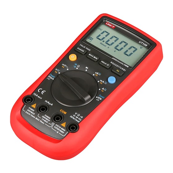
UT108
Operating manual
UNI-T UT108 Operating Manual
Handheld automotive multi-purpose meters
Hide thumbs
1
2
Table Of Contents
3
4
5
6
7
8
9
10
11
12
13
14
15
16
17
18
19
20
21
22
23
24
25
26
27
28
29
30
31
32
33
34
35
36
37
38
39
40
41
42
43
44
45
46
47
48
49
50
51
52
53
54
55
56
57
58
59
60
61
62
63
64
65
66
67
68
69
70
71
72
73
74
75
76
77
78
79
80
81
82
83
84
85
86
87
88
89
90
91
92
93
94
95
page
of
95
Go
/
95
Contents
Table of Contents
Bookmarks
Table of Contents
Table of Contents
Overview
Unpacking Inspection
Safety Information
Rules for Safe Operation
Automotive Servicing Safety Guide
International Electrical Symbols
Diode
The Meter Structure
Rotary Switch
Functional Buttons
Display Symbols
Measurement Operation
Part 1 Multimeter Basic Testing
AC/DC Voltage Testing
DC Millvoltage Testing
AC/DC Current Testing
Resistance Testing
Continuity Testing
Continuity
Maintenance
General Services
Replacing the Fuses
Replacing the Battery
Advertisement
Quick Links
1
Table of Contents
2
Overview
3
The Meter Structure
4
Ac/DC Voltage Testing
5
Measurement Operation
6
Ac/DC Current Testing
7
Resistance Testing
Download this manual
P/N:110401102526
Table of
Contents
Previous
Page
Next
Page
1
2
3
4
5
Advertisement
Table of Contents
Need help?
Do you have a question about the UT108 and is the answer not in the manual?
Ask a question
Questions and answers
Related Manuals for UNI-T UT108
Measuring Instruments UNI-T UT118A Operating Manual
Pen type meters (2 pages)
Measuring Instruments UNI-T UT118A Operating Manual
Pen type meters (2 pages)
Measuring Instruments UNI-T UT118A Operating Manual
Pen type meters (2 pages)
Measuring Instruments UNI-T UT118A Operating Manual
Pen type meters (2 pages)
Measuring Instruments UNI-T UT181A Operating Manual
(41 pages)
Measuring Instruments UNI-T UT109 Operating Manual
Handheld automotive multi-purpose meters (95 pages)
Measuring Instruments UNI-T UT123T Manual
(9 pages)
Measuring Instruments UNI-T UT118C User Manual
Pen type meter (19 pages)
Measuring Instruments UNI-T UT602 Operating Manual
Digital inductance capacitance meter (26 pages)
Measuring Instruments UNI-T UT241 Operating Manual
Clamp meters (27 pages)
Measuring Instruments UNI-T UT30A Operating Manual
(33 pages)
Measuring Instruments UNI-T UT253A Operating Manual
Large jaw leakage current clamp meter (12 pages)
Measuring Instruments UNI-T UT255A Operating Manual
High voltage clamp ammeters (20 pages)
Measuring Instruments UNI-T UT385 User Manual
Laser power meter (12 pages)
Measuring Instruments UNI-T UT620C Operating Manual
Digital micro oh meter (12 pages)
Measuring Instruments UNI-T UT-P4100A Manual
Low frequency acdc current probe (12 pages)
This manual is also suitable for:
Ut109
Table of Contents
Print
Rename the bookmark
Delete bookmark?
Delete from my manuals?
Login
Sign In
OR
Sign in with Facebook
Sign in with Google
Upload manual
Upload from disk
Upload from URL


Need help?
Do you have a question about the UT108 and is the answer not in the manual?
Questions and answers