Table of Contents
Advertisement
Quick Links
Advertisement
Table of Contents

Subscribe to Our Youtube Channel
Related Manuals for Keysight Technologies InfiniiMax Ultra Series


Summary of Contents for Keysight Technologies InfiniiMax Ultra Series
- Page 1 Keysight InfiniiMax Ultra Series Probe Amplifiers and Probe Heads User’s Guide...
- Page 2 Notices Technology Licenses © Keysight Technologies, 2021 technical data. 52.227-14 (June 1987) or DFAR 252.227-7015 (b)(2) (November No part of this manual may be reproduced in The hardware and/or software described in 1995), as applicable in any technical data. any form or by any means (including elec-...
-
Page 3: Table Of Contents
InfiniiMax Ultra Series Probe Amplifiers Key Features Compatibility with Keysight Oscilloscopes 2 Compatible Probe Heads and Accessories - Overview Supported Probe Heads for InfiniiMax Ultra Series Probe Amplifiers InfiniiMax Ultra Series Probe Family Diagram When to Use Which Recommended Probe Head... - Page 4 Connecting the MX0106A Probe Head to DUT Soldering the MX0106A Probe Head to DUT Extreme Temperature Testing with the MX0106A Probe Head 8 N2839A InfiniiMax II Browser Probe Head Overview N2839A Browser Probe Head Components InfiniiMax Ultra Series Probe Amplifiers & Probe Heads User’s Guide...
- Page 5 Using the N5425B Probe Head with N2884A Fine Wire ZIF Tip Maintaining the N5425B Probe Head Fine Wire ZIF Tips Handling Precautions 11 Configuring Infiniium Software for InfiniiMax Ultra Series Probe Amplifiers and Probe Heads Selecting Components Used in the Probing Setup Configuring Offset Behavior...
- Page 6 Cautions Associated with Extreme Temperature Testing Probing Ungrounded Devices Blocking out the DC Component of the Input Signal 13 InfiniiMax Ultra Series Probe Amplifiers and Probe Heads System Responses Typical Corrected System Frequency Response Typical Step Response of Corrected System...
- Page 7 15 Returning a Probe/Probe Head for Repair/Service Contacting Keysight Technologies for Technical Assistance 16 Replacement Parts MX0100A Probe Head MX0106A Probe Head N2839A Browser Head Other Replacement Parts Index InfiniiMax Ultra Series Probe Amplifiers & Probe Heads User’s Guide...
- Page 8 InfiniiMax Ultra Series Probe Amplifiers & Probe Heads User’s Guide...
-
Page 9: Mx0020A/21A/22A/24A/25A Probe Amplifiers - Overview
InfiniiMax Ultra Series Probe Amplifiers and Probe Heads User’s Guide MX0020A/21A/22A/24A/25A Probe Amplifiers - Overview Introduction InfiniiMax Ultra Series Probe Amplifiers Key Features Compatibility with Keysight Oscilloscopes This user’s guide describes how to set up and use the following InfiniiMax Ultra series probe amplifiers and probe heads. -
Page 10: Introduction
MX0020A/21A/22A/24A/25A Probe Amplifiers - Overview Introduction The InfiniiMax Ultra series probe amplifiers provide high bandwidth (maximum up to 25 GHz) and an RC input impedance profile for extremely low mid-band loading, which is necessary to address modern high-speed probing requirements. - Page 11 Allows you to connect the DUT ground to the probe amplifier ground using a ground lead wire. This is needed if the DUT is not grounded to the oscilloscope via the AC mains ground (see page 158). InfiniiMax Ultra Series Probe Amplifiers & Probe Heads User’s Guide...
-
Page 12: Infiniimax Ultra Series Probe Amplifiers Key Features
139 to know how to set up and use these options. InfiniiMode All InfiniiMax Ultra series probe amplifiers are InfiniiMode capable. An InfiniiMode Capable capable probe amplifier when used with an InfiniiMode capable probe head allows you to make single-ended A, single-ended B, differential as well as common-mode measurements using the same probing setup. - Page 13 Therefore, if, for example, you use it with the MX0106A probe head, which supports a 23 GHz bandwidth, then this combination would produce a system with a 23 GHz bandwidth. InfiniiMax Ultra Series Probe Amplifiers & Probe Heads User’s Guide...
-
Page 14: Compatibility With Keysight Oscilloscopes
Keysight periodically releases software updates to support your probe, fix known defects, and incorporate product enhancements. To download the latest firmware, go to www.Keysight.com search for your oscilloscope’s model number. Click the “Drivers, Firmware & Software” tab under the Technical Support link. InfiniiMax Ultra Series Probe Amplifiers & Probe Heads User’s Guide... -
Page 15: Compatible Probe Heads And Accessories - Overview
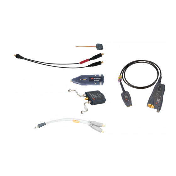
N5448B (25cm) / N2823A (1m) Coaxial Phase Matched Cable Pair N2812B (1m) High Performance Input Cable E2669B Differential Connectivity Kit This chapter provides an overview of various probe heads and accessories that are available for use with the InfiniiMax Ultra series probe amplifiers. -
Page 16: Supported Probe Heads For Infiniimax Ultra Series Probe Amplifiers
Amplifiers A probe amplifier connects to a DUT via a probe head. When using an InfiniiMax Ultra series probe amplifier, you can choose from a wide variety of probe heads and accessories to support your specific probing and DUT connectivity requirements. -
Page 17: Infiniimax Ultra Series Probe Family Diagram
Compatible Probe Heads and Accessories - Overview InfiniiMax Ultra Series Probe Family Diagram InfiniiMax Ultra Series Probe Amplifiers & Probe Heads User’s Guide... -
Page 18: When To Use Which Recommended Probe Head
3. N2839A Differential Browser Probe Head (refer to page 83 for details) • Hand-held browsing for general purpose 21 GHz 0.20 pF 0.34 pF troubleshooting of a circuit board • Adjustable probe tips for different circuit geometries InfiniiMax Ultra Series Probe Amplifiers & Probe Heads User’s Guide... - Page 19 0.72 pF 0.71 pF head and tip. • Used with an N2849A QuickTip. • Permanently solder any number of QuickTips to your DUT and effortlessly connect and disconnect probe head to each QuickTip InfiniiMax Ultra Series Probe Amplifiers & Probe Heads User’s Guide...
- Page 20 MX0025A, which supports a 25 GHz bandwidth, with a MX0106A, which supports a 23 GHz bandwidth, would produce a system with a 23 GHz bandwidth. b Capacitance seen by differential signals c Capacitance seen by single-ended signals InfiniiMax Ultra Series Probe Amplifiers & Probe Heads User’s Guide...
-
Page 21: Other Recommended Accessories And Kits
Other Recommended Accessories and Kits In addition to the probe heads listed in the previous section, there are a number of kits and accessories available for use with the InfiniiMax Ultra series probe amplifiers. This section provides an overview to these recommended accessories and kits. You can either order these at the time of ordering the probe amplifier or separately later. -
Page 22: N2881A Infiniimax Dc Blocking Capacitors
For instance, you can use the tools available in this kit while soldering the lead wires of the MX0100A Micro probe head to a DUT (see page 61 for details). InfiniiMax Ultra Series Probe Amplifiers & Probe Heads User’s Guide... - Page 23 Compatible Probe Heads and Accessories - Overview Double-sided Foam Tape Regular Solder Wire Low Temperature Solder Wire Cutting Tweezers Straight Tweezers Probe Tip Wire Kapton Tape Figure 4 MX0102A soldering toolkit contents InfiniiMax Ultra Series Probe Amplifiers & Probe Heads User’s Guide...
- Page 24 Clip as short as possible using the cutting tweezers included in the kit. a You can reorder these items using the part numbers included in the table above. InfiniiMax Ultra Series Probe Amplifiers & Probe Heads User’s Guide...
-
Page 25: N2852A Autoprobe Ii To Autoprobe Iii Adapter
>13 GHz of bandwidth such as MX0024A 20 GHz probe amplifier. E2655C PV/Deskew Fixture Kit • To know how to use this fixture for deskew/calibration of your probe, refer to the E2655C user’s guide. InfiniiMax Ultra Series Probe Amplifiers & Probe Heads User’s Guide... -
Page 26: N5448B (25Cm) / N2823A (1M) Coaxial Phase Matched Cable Pair
5 psec, and the cable supports up to 40 GHz. For detailed specifications of these cables, refer to the user’s guide available in the Document Library tab of www.keysight.com/find/N5448B. InfiniiMax Ultra Series Probe Amplifiers & Probe Heads User’s Guide... -
Page 27: N2812B (1M) High Performance Input Cable
The E2669B differential connectivity kit provides multiple quantities of the: • following three InfiniiMax I probe heads supported for use with the InfiniiMax Ultra probe amplifier. • accessories needed for these three probe heads. InfiniiMax Ultra Series Probe Amplifiers & Probe Heads User’s Guide... - Page 28 Compatible Probe Heads and Accessories - Overview Figure 6 E2669B Differential Connectivity Kit (not to scale) InfiniiMax Ultra Series Probe Amplifiers & Probe Heads User’s Guide...
- Page 29 Either value produces a response that is well within specifications. If you have some of the older 100W resistors, ensure that you use either two 100W or two 91W resistors. Do not mix them. InfiniiMax Ultra Series Probe Amplifiers & Probe Heads User’s Guide...
- Page 30 Compatible Probe Heads and Accessories - Overview InfiniiMax Ultra Series Probe Amplifiers & Probe Heads User’s Guide...
-
Page 31: Safety And Regulatory Information
InfiniiMax Ultra Series Probe Amplifiers and Probe Heads User’s Guide Safety and Regulatory Information Safety Checks and Warnings Instrument Markings and Symbols... -
Page 32: Safety Checks And Warnings
Periodically inspect the probe and probe wires to check for any damage. WARNING Do Not Operate With Visible or Suspected Failures. If you suspect there is damage, have it inspected by a Keysight authorized service personnel. InfiniiMax Ultra Series Probe Amplifiers & Probe Heads User’s Guide... - Page 33 (power cable) without a protective conductor (grounding). Grounding one conductor of a two-conductor outlet is not sufficient protection. Capacitors inside the instrument may retain a charge even if the instrument is WARNING disconnected from its source of supply. InfiniiMax Ultra Series Probe Amplifiers & Probe Heads User’s Guide...
- Page 34 The CE mark is a registered trademark of the European Community. ISM GRP 1-A denotes the instrument is an Industrial Scientific and Medical Group 1 Class A product. ICES/NMB-001 indicates product compliance with the Canadian Interference-Causing Equipment Standard. InfiniiMax Ultra Series Probe Amplifiers & Probe Heads User’s Guide...
- Page 35 InfiniiMax Ultra Series Probe Amplifiers and Probe Heads User’s Guide Proper Handling of Probe Amplifier and Probe Heads Avoiding Damage and Costly Repairs Using a static-safe workstation Probe Amplifier and Probe Heads Handling Precautions Precautions while Connecting and Disconnecting Probe Heads...
-
Page 36: Proper Handling Of Probe Amplifier And Probe Heads
Purchase acceptable ESD accessories from your local supplier. You can plug the ESD wrist strap into the front-panel ground socket of the oscilloscope as seen in the following picture. InfiniiMax Ultra Series Probe Amplifiers & Probe Heads User’s Guide... - Page 37 Wrist Strap Connected to Oscilloscope’s Ground Socket These techniques for a static-safe workstation should not be WARNING used when working on circuitry with a voltage potential greater than 500 volts. InfiniiMax Ultra Series Probe Amplifiers & Probe Heads User’s Guide...
-
Page 38: Probe Amplifier And Probe Heads Handling Precautions
This can be done in a similar manner to how garden hoses or extension cords are typically coiled. InfiniiMax Ultra Series Probe Amplifiers & Probe Heads User’s Guide... -
Page 39: Precautions While Connecting And Disconnecting Probe Heads
• For the MX0105A SMA head or the N2839A browser probe head, you can safely move the probe head from one location to another without having to first break the amplifier-to-head connection. InfiniiMax Ultra Series Probe Amplifiers & Probe Heads User’s Guide... - Page 40 This is because some soldering-iron tips can hold a charge which can damage the probe amplifier. InfiniiMax Ultra Series Probe Amplifiers & Probe Heads User’s Guide...
-
Page 41: Strain Relieving Techniques For Probe Heads
(only use the low temperature hot glue on the probe head cables). Correct securing methods Incorrect securing method with glue on the probe head tip Figure 9 Correct and incorrect strain relief techniques InfiniiMax Ultra Series Probe Amplifiers & Probe Heads User’s Guide... -
Page 42: Tack-Putty
Only use low-temperature hot glue. To remove the hot glue, warm CAUTION it with a heat gun set on low. Only heat the hot glue enough to remove it. Figure 12 Probe Secured Using Low-Temperature Hot Glue InfiniiMax Ultra Series Probe Amplifiers & Probe Heads User’s Guide... -
Page 43: Velcro Pads
The provided Velcro pads can be used to secure your probe amplifier casing to the board. Attach Velcro dots to the probe amplifier as well as the circuit board as shown in the figure below. Figure 13 Using Velcro Dots InfiniiMax Ultra Series Probe Amplifiers & Probe Heads User’s Guide... -
Page 44: Tips For Soldering Probe Heads
Soldering Guidelines for Keysight InfiniiMax Probes Application Note (publication number 5992-3350EN) • “Soldering an MX0100A Probe Head to DUT" on page 61 • “Step 3 - Solder the N5426A ZIF Tip to the DUT" on page 114 InfiniiMax Ultra Series Probe Amplifiers & Probe Heads User’s Guide... -
Page 45: Cleaning
Wipe with clean water and then dry thoroughly with a clean cloth. Make sure that the probe amplifier / probe head is completely dry before reconnecting it to an oscilloscope or circuit under test. InfiniiMax Ultra Series Probe Amplifiers & Probe Heads User’s Guide... - Page 46 Proper Handling of Probe Amplifier and Probe Heads InfiniiMax Ultra Series Probe Amplifiers & Probe Heads User’s Guide...
-
Page 47: Characteristics And Specifications
InfiniiMax Ultra Probe Heads Characteristics Environmental and General Characteristics The tables in this chapter list the specifications and characteristics for the InfiniiMax Ultra series probe amplifiers and their recommended probe heads. All entries included in this chapter are characteristics unless otherwise N OT E noted. -
Page 48: Infiniimax Ultra Series Probe Amplifiers Warranted Specifications
Specification MX0025A 25 GHz MX0100A Micro Bandwidth 25 GHz (with 60 mil probe Probe Amplifier Probe Head leads) DC Input = 50 kW ±2% diff Resistance = 25 kW ±2% InfiniiMax Ultra Series Probe Amplifiers & Probe Heads User’s Guide... -
Page 49: Infiniimax Ultra Series Probe Amplifier Characteristics
Input referred noise, in 25.0 nV/√(Hz) @ 1:1 16.0 nV/√(Hz) @ 1:1.56 spectral density 39.7 nV/√(Hz) @ 4:1 25.5 nV/√(Hz) @ 2.57:1 45.0 nV/√(Hz) @ 7.6:1 29.0 nV/√(Hz) @ 4.87:1 InfiniiMax Ultra Series Probe Amplifiers & Probe Heads User’s Guide... - Page 50 See maximum input power peak Input Voltage a Delay can be skewed relative to other signals. b Mains isolated is for measurements performed on circuits not directly connected to a mains supply. InfiniiMax Ultra Series Probe Amplifiers & Probe Heads User’s Guide...
-
Page 51: Infiniimax Ultra Probe Heads Characteristics
- N5380B Differential SMA Probe Head - N5425B ZIF Probe Head with N5451A Long Wire ZIF Tips - E2677B Differential Solder-in Probe Head - E2678B Differential Socketed Probe Head - E2675B Differential Browser Probe Head InfiniiMax Ultra Series Probe Amplifiers & Probe Heads User’s Guide... -
Page 52: Environmental And General Characteristics
Refer to the Dimensions section in the chapter dedicated to each probe head in this guide. Weight 0.8 kg Pollution Degree Pollution Degree 2 Normally only non-conductive pollution occurs. Occasionally, however, a temporary conductivity caused by condensation must be expected. InfiniiMax Ultra Series Probe Amplifiers & Probe Heads User’s Guide... -
Page 53: Mx0100A Infiniimax Micro Probe Head
InfiniiMax Ultra Series Probe Amplifiers and Probe Heads User’s Guide MX0100A InfiniiMax Micro Probe Head Overview MX0100A Probe Head Kit Components Connecting the MX0100A Probe Head to DUT InfiniiMode Capable MX0100A Dimensions MX0100A Input Impedance Setting up and Using the MX0100A Probe Head... -
Page 54: Overview
For connection to a DUT, it has pre-wired probe tip leads that allow solder-in connection to very small, fine pitch targets. Figure 15 MX0100A probe head connected to DUT and InfiniiMax Ultra probe amplifier InfiniiMax Ultra Series Probe Amplifiers & Probe Heads User’s Guide... -
Page 55: Mx0100A Probe Head Kit Components
The MX0100A probe head is InfiniiMode capable when used with an InfiniiMax Ultra series probe amplifier. page 150 for details on how to make InfiniiMode measurements. MX0100A Dimensions All dimensions in Figure 16 are in mm [inches]. InfiniiMax Ultra Series Probe Amplifiers & Probe Heads User’s Guide... - Page 56 MX0100A InfiniiMax Micro Probe Head Figure 16 MX0100A Probe Head Dimensions InfiniiMax Ultra Series Probe Amplifiers & Probe Heads User’s Guide...
-
Page 57: Mx0100A Input Impedance
“InfiniiMax Ultra Series Probe Amplifiers and NOT E Probe Heads System Responses" on page 161 to get a typical corrected frequency response and CMRR for the MX0100A probe head and InfiniiMax Ultra probe amplifier combination. InfiniiMax Ultra Series Probe Amplifiers & Probe Heads User’s Guide... - Page 58 The following SPICE model can be used to predict the probe loading effects of the InfiniiMax Ultra probe amplifier and MX0100A probe head combination. Figure 17 SPICE Model for the input impedance of the MX0100A Micro Probe Head InfiniiMax Ultra Series Probe Amplifiers & Probe Heads User’s Guide...
- Page 59 Rp3 4 11 25k RG0 11 12 130.8 L2 12 0 964.6p L3 11 0 30u .END Figure 18 Input Impedances (Z Modeled and Z Measured) for the MX0100A Probe Head InfiniiMax Ultra Series Probe Amplifiers & Probe Heads User’s Guide...
-
Page 60: Setting Up And Using The Mx0100A Probe Head
The trim gauge template displays two lengths: 3.4 mm and 1.5 mm. Choose the correct length as per your DUT. Using the cutting tweezers, trim the lead wires even with the trim lines. InfiniiMax Ultra Series Probe Amplifiers & Probe Heads User’s Guide... -
Page 61: Soldering An Mx0100A Probe Head To Dut
This cleans the solder joint and allows for easier flowing solder and quicker dwell times. Add solder to existing test points on DUT, if necessary. Heat momentarily and do not dwell any longer than necessary! InfiniiMax Ultra Series Probe Amplifiers & Probe Heads User’s Guide... - Page 62 0460-3122 included in the MX0102A Soldering Toolkit). You can also use putty, Velcro or low temperature hot glue instead. Connect the soldered MX0100A probe head to the InfiniMax probe amplifier using the supplied MX0103A bullet adapter. InfiniiMax Ultra Series Probe Amplifiers & Probe Heads User’s Guide...
-
Page 63: Attaching Ground Lead Wires To An Mx0100A Probe Head
InfiniiMode setup. page 152 for this procedure. This step is not required if you are making a single-ended or a differential NOT E measurement only. Ground Lead Wires InfiniiMax Ultra Series Probe Amplifiers & Probe Heads User’s Guide... -
Page 64: Maintaining The Mx0100A Probe Head
• While moving a soldered MX0100A probe head, always ensure that you do not twist, pull, tightly bend, or apply force near the probe head’s cable housing. Figure 21 Example of correct movement of MX0100A probe head InfiniiMax Ultra Series Probe Amplifiers & Probe Heads User’s Guide... - Page 65 • or engage a flat screwdriver on the notch provided on the bullet adapter and gently disconnect the probe head from bullet adapter. InfiniiMax Ultra Series Probe Amplifiers & Probe Heads User’s Guide...
- Page 66 For a damaged probe head, the resistance measurement between the MX0100A probe head tip wire and the center conductor of the SMP connector of the MX0100A is displayed as Infinite. Figure 24 Resistance measurement for a damaged MX0100A probe head InfiniiMax Ultra Series Probe Amplifiers & Probe Heads User’s Guide...
-
Page 67: Replacing The Mx0100A Probe Tip Lead Wires
To avoid burning and damage to the probe head, do not keep the CAUTION soldering iron in contact with the tip any longer than necessary. The solder joint quickly melts and releases the wire. InfiniiMax Ultra Series Probe Amplifiers & Probe Heads User’s Guide... - Page 68 Do not dwell on the joint with the solder iron any longer than needed. The solder should flow off the soldering iron tip into the joint. If it does not flow, then sufficient flux may not have been used. InfiniiMax Ultra Series Probe Amplifiers & Probe Heads User’s Guide...
- Page 69 MX0100A InfiniiMax Micro Probe Head Cut the extra wire off using a cutting tweezer (Keysight part number 8710-2838 included in the MX0102A Soldering Toolkit). Remove the Kapton tape. InfiniiMax Ultra Series Probe Amplifiers & Probe Heads User’s Guide...
-
Page 70: Extreme Temperature Testing With The Mx0100A Probe Head
To know more about how to use MX0100A in extreme temperatures and the associated cautions, refer to “Extreme Temperature Probing" on page 156. InfiniiMax Ultra Series Probe Amplifiers & Probe Heads User’s Guide... - Page 71 InfiniiMax Ultra Series Probe Amplifiers and Probe Heads User’s Guide MX0106A InfiniiMax Ultra Differential Solder-in Probe Head Overview InfiniiMode Capable MX0106A Probe Head Supplied Accessories MX0106A Dimensions MX0106A Input Impedance Setting up and Using the MX0106A Probe Head Adjusting the Spacing between MX0106A Wires...
-
Page 72: Mx0106A Infiniimax Ultra Differential Solder-In Probe Head
MX0106A probe head and Ultra series probe amplifiers. InfiniiMode Capable This probe head is InfiniiMode capable when used with an InfiniiMax Ultra series probe amplifier. See page 150 for details on how to make InfiniiMode measurements. - Page 73 MX0106A InfiniiMax Ultra Differential Solder-in Probe Head Figure 25 MX0106A Probe Head Dimensions InfiniiMax Ultra Series Probe Amplifiers & Probe Heads User’s Guide...
-
Page 74: Mx0106A Input Impedance
“InfiniiMax Ultra Series Probe Amplifiers and NOT E Probe Heads System Responses" on page 161 to get a typical corrected frequency response and CMRR for the InfiniiMax Ultra probe amplifier and probe head combination. InfiniiMax Ultra Series Probe Amplifiers & Probe Heads User’s Guide... - Page 75 The following SPICE model can be used to predict the probe loading effects of the InfiniiMax RC probe and MX0106A probe head combination. Figure 26 SPICE Model for the input impedance of the MX0106A Probe Head InfiniiMax Ultra Series Probe Amplifiers & Probe Heads User’s Guide...
- Page 76 Rp3 4 11 25k RG0 11 12 96.1286 L2 12 0 300.174p L3 11 0 30u .END Figure 27 Input Impedances (Z Modeled and Z Measured) for the MX0106A Probe Head InfiniiMax Ultra Series Probe Amplifiers & Probe Heads User’s Guide...
-
Page 77: Setting Up And Using The Mx0106A Probe Head
Installing / Replacing the MX0106A Probe Head Wire Leads The lead wires of the MX0106A probe head are replaceable. Table 14 Required Wire Type Part Wire Diameter Number 0.007 inch (tin-plated nickel wires) for signal leads 01169-81301 InfiniiMax Ultra Series Probe Amplifiers & Probe Heads User’s Guide... - Page 78 If using a tweezers clamp, grip the probe head tip either on the sides or at the top and bottom. Figure 29 Clamping the MX0106A Probe Head InfiniiMax Ultra Series Probe Amplifiers & Probe Heads User’s Guide...
- Page 79 Cut the wires that protrude on the bottom side of the probe head board even with the solder pad. Place the wires through the hole in the supplied trim gauge with the probe head perpendicular to the trim gauge. InfiniiMax Ultra Series Probe Amplifiers & Probe Heads User’s Guide...
- Page 80 Figure 31 Cutting Wires Flush with Gauge Each wire lead needs to be trimmed to 0.89 mm to fit the hole in the pc board as shown in the following figure. InfiniiMax Ultra Series Probe Amplifiers & Probe Heads User’s Guide...
-
Page 81: Connecting The Mx0106A Probe Head To Dut
Do not leave the soldering iron in contact with the probe head for CAUTION more than a few seconds at a time. For additional tips, refer to the topic “Tips for Soldering Probe Heads" on page 44. InfiniiMax Ultra Series Probe Amplifiers & Probe Heads User’s Guide... -
Page 82: Extreme Temperature Testing With The Mx0106A Probe Head
To know more about how to use MX0106A in extreme temperatures and the associated cautions, refer to “Extreme Temperature Probing" on page 156. InfiniiMax Ultra Series Probe Amplifiers & Probe Heads User’s Guide... - Page 83 InfiniiMax Ultra Series Probe Amplifiers and Probe Heads User’s Guide N2839A InfiniiMax II Browser Probe Head Overview N2839A Browser Probe Head Components N2839A Supplied Accessories N2839A Dimensions N2839A Input Impedance Using the N2839A Browser Probe Head Adjusting Spacing Between the Browser Tips...
-
Page 84: N2839A Infiniimax Ii Browser Probe Head
Spring-loaded tips work best when these are either partially or fully compressed and are protected against over compression damage. InfiniiMax Ultra Series Probe Amplifiers & Probe Heads User’s Guide... -
Page 85: N2839A Dimensions
Keep the protective end cap on the browser when the browser is not in use. To purchase additional tips, order the N2837A kit that contains 20 N OT E spring-loaded tips and 20 straight tips. N2839A Dimensions InfiniiMax Ultra Series Probe Amplifiers & Probe Heads User’s Guide... -
Page 86: N2839A Input Impedance
The following SPICE model can be used to predict the probe loading effects of the N2839A probe head. The S-parameters and spice models for the N2839A probe head remain the NOT E same for the spring-loaded tips and straight tips supplied with the browser. InfiniiMax Ultra Series Probe Amplifiers & Probe Heads User’s Guide... - Page 87 6 3 139.7 r16 10 17 139.7 csrc1 3 7 35.6f l2 7 8 4.03n r4 8 4 1553.6 c4 17 11 93.1f c6 4 15 93.1f l6 11 12 .164n InfiniiMax Ultra Series Probe Amplifiers & Probe Heads User’s Guide...
- Page 88 4 17 25k r11 17 18 40.54 l7 18 0 .205n l8 17 0 47.23u ends Figure 35 Input Impedances (Z Modeled and Z Measured) for the N2839A Probe Head InfiniiMax Ultra Series Probe Amplifiers & Probe Heads User’s Guide...
-
Page 89: Using The N2839A Browser Probe Head
N OT E response. Hands-Free Probing For hands-free stability, you can: • either mount the N2839A browser on an N2784/5A or N2787A probe positioner as displayed in the following figure. InfiniiMax Ultra Series Probe Amplifiers & Probe Heads User’s Guide... - Page 90 Figure 37 Location and Dimensions of Mounting Hole Do not allow the mounting screw to penetrate more than 4 mm into CAUTION the browser’s mounting hole. Torque the mounting screw to 0.09 Nm (0.8 lb-in.). InfiniiMax Ultra Series Probe Amplifiers & Probe Heads User’s Guide...
-
Page 91: Maintaining The N2839A Probe Head
When sending the probe head for repair or service, you need the serial number of the probe head. The N2839A’s serial number is located inside the browser’s head-to-amplifier connection as shown in the following figure. InfiniiMax Ultra Series Probe Amplifiers & Probe Heads User’s Guide... -
Page 92: Replacing The Browser's Tips
Using the tweezers, align the new tip with the browser’s tip socket and gently insert the tip while avoiding any twisting motion. InfiniiMax Ultra Series Probe Amplifiers & Probe Heads User’s Guide... - Page 93 Figure 40 Inserting a Tip Hold the probe vertically and gently press the tip on a hard surface, such as the tweezers, to properly seat the tip. InfiniiMax Ultra Series Probe Amplifiers & Probe Heads User’s Guide...
- Page 94 N2839A InfiniiMax II Browser Probe Head InfiniiMax Ultra Series Probe Amplifiers & Probe Heads User’s Guide...
- Page 95 InfiniiMax Ultra Series Probe Amplifiers and Probe Heads User’s Guide MX0105A InfiniiMax Ultra Differential SMA Probe Head Overview MX0105A Probe Head Components InfiniiMode Capable MX0105A Dimensions MX0105A SPICE Subcircuit Data MX0105A Input Return Loss (S11)
-
Page 96: Mx0105A Infiniimax Ultra Differential Sma Probe Head
These cables are formed in an offset configuration allowing you to use these in variable spacing between connection points. These cables can be spread out to a maximum of 91.7 mm. InfiniiMax Ultra Series Probe Amplifiers & Probe Heads User’s Guide... -
Page 97: Infiniimode Capable
Document Library tab of www.keysight.com/find/N5448B. InfiniiMode Capable The MX0105A probe head is InfiniiMode capable when used with an InfiniiMax Ultra series probe amplifier. See page 150 for details on how to make InfiniiMode measurements. InfiniiMax Ultra Series Probe Amplifiers & Probe Heads User’s Guide... -
Page 98: Mx0105A Dimensions
MX0105A InfiniiMax Ultra Differential SMA Probe Head MX0105A Dimensions Figure 42 MX0105A Dimensions (All dimensions are in mm [inches]) InfiniiMax Ultra Series Probe Amplifiers & Probe Heads User’s Guide... -
Page 99: Mx0105A Spice Subcircuit Data
“InfiniiMax Ultra Series Probe Amplifiers and NOT E Probe Heads System Responses" on page 161 to get a typical corrected frequency response and CMRR for the InfiniiMax Ultra probe amplifier and MX0105A probe head combination. InfiniiMax Ultra Series Probe Amplifiers & Probe Heads User’s Guide... -
Page 100: Mx0105A Input Return Loss (S11)
The graph displayed below therefore does not include the probe amplifier being used. Figure 43 MX0105A Input Return Loss (S11) InfiniiMax Ultra Series Probe Amplifiers & Probe Heads User’s Guide... -
Page 101: N5425B Infiniimax Differential Zif Probe Head
InfiniiMax Ultra Series Probe Amplifiers and Probe Heads User’s Guide N5425B InfiniiMax Differential ZIF Probe Head Overview Supported ZIF Tips N5425B Probe Head and ZIF Tips Dimensions N5425B Input Impedance Using the N5425B Probe Head with N5426A ZIF Tips Step 1 - Remove N5426A ZIF Tip from Packaging... -
Page 102: Overview
Supported ZIF Tips The N5425B probe head does not come with any ZIF probe tips. You need to separately order the supported ZIF tips matching your specific probing requirements. InfiniiMax Ultra Series Probe Amplifiers & Probe Heads User’s Guide... - Page 103 Bandwidth applicable for the specific ZIF tip + N5425B probe head + MX0025A probe amplifier combination b For additional long wire ZIF resistor leads, order 1NC3-1091 (qty 1). c The available bandwidth decreases as the span between the long wire tip leads increases. InfiniiMax Ultra Series Probe Amplifiers & Probe Heads User’s Guide...
-
Page 104: N5425B Probe Head And Zif Tips Dimensions
N5425B InfiniiMax Differential ZIF Probe Head N5425B Probe Head and ZIF Tips Dimensions Figure 45 N5425B ZIF Probe Head Dimensions with N5426A ZIF Tip Attached InfiniiMax Ultra Series Probe Amplifiers & Probe Heads User’s Guide... - Page 105 N5425B InfiniiMax Differential ZIF Probe Head Figure 46 N2884A Fine Wire ZIF Tip Dimensions InfiniiMax Ultra Series Probe Amplifiers & Probe Heads User’s Guide...
-
Page 106: N5425B Input Impedance
“InfiniiMax Ultra Series Probe Amplifiers and NOT E Probe Heads System Responses" on page 161 to get a typical corrected frequency response and CMRR for the MX0025A probe amplifier and probe head combination. InfiniiMax Ultra Series Probe Amplifiers & Probe Heads User’s Guide... -
Page 107: Spice Model Of N5425B Probe Head With N5426A Zif Tip Attached
• Rc (or Zc) will depend on the DUT circuit. • vplus connected to DUT plus signal • vminus connected to DUT minus signal. • Input impedance is defined to be (vplus - vminus)/i(vsplus) InfiniiMax Ultra Series Probe Amplifiers & Probe Heads User’s Guide... -
Page 108: Spice Deck Of N5425B Probe Head With N5426A Zif Tip Attached
Rc vsplus_N DUT_Gnd 1u C1 Rp3_N C1_N 14.75f Rtipm R1_N vminus 64.35 R1 L1_N R1_N 948.2 R2 L2_N R1_N 36.88 .AC DEC 200 200k 20G SWEEP PARAM=swtch LIN 2 0 1 .PARAM swtch=1 InfiniiMax Ultra Series Probe Amplifiers & Probe Heads User’s Guide... - Page 109 Frequency (H z) Differential (Modeled) Single Ended (Modeled) Single Ended (Measured) Differential (Measured) Figure 48 Measured and Modeled Data Matching for the N5425B Probe Head with N5426A ZIF Tip Attached InfiniiMax Ultra Series Probe Amplifiers & Probe Heads User’s Guide...
-
Page 110: Spice Model Of The N5426A Zif Tip
Figure 49 SPICE Model for N5426A ZIF Tip Use this SPICE model to model the input loading for the N2884A fine wire ZIF N OT E tip as well. InfiniiMax Ultra Series Probe Amplifiers & Probe Heads User’s Guide... -
Page 111: Spice Deck Of N5426A Zif Tip
C1 Rp3_N C1_N 3.14f Rtipm R1_N vminus 98.85 R1 L1_N R1_N 451.7 R2 L2_N R1_N 2m .AC DEC 200 200k 20G SWEEP PARAM=swtch LIN 2 0 1 .PARAM swtch 1 InfiniiMax Ultra Series Probe Amplifiers & Probe Heads User’s Guide... - Page 112 N5425B InfiniiMax Differential ZIF Probe Head Ω Frequency (H z) Differential (Modeled) Single Ended (Modeled) Single Ended (Measured) Differential (Measured) Figure 50 Measured and Modeled Data Matching for the N5426A ZIF Tip InfiniiMax Ultra Series Probe Amplifiers & Probe Heads User’s Guide...
-
Page 113: Using The N5425B Probe Head With N5426A Zif Tips
ZIF tip latch in Open position open position ZIF tip ZIF Probe Head Figure 52 ZIF Tip Latch in Open Position InfiniiMax Ultra Series Probe Amplifiers & Probe Heads User’s Guide... - Page 114 There is a possibility that if a lead of the ZIF tip is inserted into a large ball of solder that is heated excessively with a soldering iron, the solder joint holding the lead onto the ZIF tip pc board could flow and the lead would come off InfiniiMax Ultra Series Probe Amplifiers & Probe Heads User’s Guide...
- Page 115 Clean the soldering iron tip and add a small amount of solder to the very tip. This may take a few tries because the solder may tend to ball up and move away from the tip. InfiniiMax Ultra Series Probe Amplifiers & Probe Heads User’s Guide...
- Page 116 Hold on the heat-shrink part of the probe head to support the ZIF tip while releasing the latch. Figure 58 Using a Non-Conductive Tool to Open the ZIF Tip’s Latch InfiniiMax Ultra Series Probe Amplifiers & Probe Heads User’s Guide...
- Page 117 N5425B InfiniiMax Differential ZIF Probe Head Figure 59 ZIF Tip with ZIF Latch Open InfiniiMax Ultra Series Probe Amplifiers & Probe Heads User’s Guide...
-
Page 118: Using The N5425B Probe Head With N2884A Fine Wire Zif Tip
Slide ZIF probe head into the arm from this direction after sliding the coax cables into the slot in the positioner arm. Figure 60 Probe Head and Tip in Positioner InfiniiMax Ultra Series Probe Amplifiers & Probe Heads User’s Guide... - Page 119 (its base is magnetic) as it is nose-heavy. If it is left resting on a surface that the metallic base cannot secure to, it will tip over and the Fine Wire ZIF tip may become damaged. InfiniiMax Ultra Series Probe Amplifiers & Probe Heads User’s Guide...
- Page 120 The picture shows the standard ZIF tip and is only meant to highlight the latch’s open position (the latch is the same on the standard and Fine Wire ZIF tips). InfiniiMax Ultra Series Probe Amplifiers & Probe Heads User’s Guide...
- Page 121 In order to prepare the IC for probing, you first need to chemically etch a large trench out of the IC. Within the trench, create at least two wells (target well and ground well) to the targeted metal layers. These wells should be approximately InfiniiMax Ultra Series Probe Amplifiers & Probe Heads User’s Guide...
- Page 122 Figure 66 ZIF Tip Wires InfiniiMax Ultra Series Probe Amplifiers & Probe Heads User’s Guide...
- Page 123 Once you see it flex, stop moving in the z-direction and use the x-y knobs on the micropositioner to wiggle the longer wire slightly. If the wire wiggles, but stays stuck in place on the IC then it was properly placed in the well. InfiniiMax Ultra Series Probe Amplifiers & Probe Heads User’s Guide...
- Page 124 Decrease the magnification of the microscope until you can see the entire length of both wires and ensure that the wires are not touching. InfiniiMax Ultra Series Probe Amplifiers & Probe Heads User’s Guide...
-
Page 125: Maintaining The N5425B Probe Head
When the Fine Wire ZIF tip is positioned under a microscope, be CAUTION very careful with the lenses of the microscope as you adjust the magnification or focus. If one of the lenses strikes the tip, it could permanently damage it. InfiniiMax Ultra Series Probe Amplifiers & Probe Heads User’s Guide... - Page 126 Turn on the device under test (DUT) only when you have verified that the wires are not touching. InfiniiMax Ultra Series Probe Amplifiers & Probe Heads User’s Guide...
-
Page 127: Configuring Infiniium Software For Infiniimax Ultra Series Probe Amplifiers And Probe Heads
InfiniiMax Ultra Series Probe Amplifiers and Probe Heads User’s Guide Configuring Infiniium Software for InfiniiMax Ultra Series Probe Amplifiers and Probe Heads Selecting Components Used in the Probing Setup Configuring Offset Behavior Calibrating your InfiniiMax Ultra Probe Calibration Overview Sequence of Calibration... -
Page 128: Selecting Components Used In The Probing Setup
Configuring Infiniium Software for InfiniiMax Ultra Series Probe Amplifiers and Probe Heads Selecting Components Used in the Probing Setup When you connect your InfiniiMax Ultra probe amplifier to a compatible Keysight oscilloscope, the amplifier is automatically detected and displayed as connected to the oscilloscope’s channel in the Infiniium software GUI. - Page 129 Configuring Infiniium Software for InfiniiMax Ultra Series Probe Amplifiers and Probe Heads Figure 71 Probe connection diagram in the Probe System section Select the checkbox displayed with the component(s) that you have used in the probing setup. The selected component(s) then get added to the probe connection diagram.
- Page 130 Configuring Infiniium Software for InfiniiMax Ultra Series Probe Amplifiers and Probe Heads After selecting components, you can select the type of probe head(s) being used so that the oscilloscope can apply the appropriate correction filter (S parameter) for the probe head(s). Click Select Head... in the Probe Head block of the diagram.
-
Page 131: Configuring Offset Behavior
Configuring Infiniium Software for InfiniiMax Ultra Series Probe Amplifiers and Probe Heads Configuring Offset Behavior You can configure the offset behavior to ensure that you get the maximum performance and dynamic range from your InfiniiMax Ultra probe amplifier. By applying an offset, most or all of the DC component can be subtracted and the signal can be positioned to better utilize the input’s available dynamic range. - Page 132 Configuring Infiniium Software for InfiniiMax Ultra Series Probe Amplifiers and Probe Heads In the Probe Offset dialog box, the probe offset behavior options are available based on your choice of measurement mode for your probe amplifier. For example, if you select the Differential measurement mode, then both Normal Offset and Probe Offset options are available as you can use this mode to probe differential and single-ended signals.
-
Page 133: Calibrating Your Infiniimax Ultra Probe
Configuring Infiniium Software for InfiniiMax Ultra Series Probe Amplifiers and Probe Heads Calibrating your InfiniiMax Ultra Probe To get the highest measurement accuracy, you must calibrate your probe before you start using it. Calibration Overview The following types of calibrations are available for the InfiniiMax Ultra series probe amplifiers. -
Page 134: Performing Dc Gain / Offset And Skew Calibration
Configuring Infiniium Software for InfiniiMax Ultra Series Probe Amplifiers and Probe Heads Performing DC Gain / Offset and Skew Calibration The probe calibration and deskew is a guided procedure that you initiate from the oscilloscope’s Probe Calibration dialog box. Accessories Needed... - Page 135 Configuring Infiniium Software for InfiniiMax Ultra Series Probe Amplifiers and Probe Heads The next screen in the guided procedure requires the usage of the MX0104A deskew fixture in this calibration. To use the MX0104A deskew fixture: Connect the 50 Ω terminator to the MX0104A fixture. This terminator is provided with the fixture.
- Page 136 Configuring Infiniium Software for InfiniiMax Ultra Series Probe Amplifiers and Probe Heads For the solder-in and ZIF probe heads, adjust the shape of the probe head tips as shown in the following figure before you clamp these to the deskew fixture.
- Page 137 Configuring Infiniium Software for InfiniiMax Ultra Series Probe Amplifiers and Probe Heads spring loaded clamps, ground plane, and center conductor (signal path) are labeled in the following figure. Do not press down with much force to avoid snapping off CAUTION the fixture from the Cal Out connection.
- Page 138 Configuring Infiniium Software for InfiniiMax Ultra Series Probe Amplifiers and Probe Heads You can verify whether or not the probe head’s leads are correctly NOT E connected to the MX0104A deskew fixture by pressing the oscilloscope’s autoscale button. If a stable step is displayed on screen, it indicates a good connection.
-
Page 139: Choosing The Probe Response Option
Configuring Infiniium Software for InfiniiMax Ultra Series Probe Amplifiers and Probe Heads Choosing the Probe Response Option What is Probe Response Correction? The method used to define your probe's response. There are two common methods for correcting a probe's response: •... -
Page 140: Source Estimate Option Availability
Configuring Infiniium Software for InfiniiMax Ultra Series Probe Amplifiers and Probe Heads Source Estimate Option Availability The Source Estimate option is available for the following combinations of probe amplifiers, probe heads, orientation of probe head in the probing setup, and measurement mode. -
Page 141: How To Determine The Currently Active Probe Response Option
Configuring Infiniium Software for InfiniiMax Ultra Series Probe Amplifiers and Probe Heads How to Determine the Currently Active Probe Response Option Each probe response option has an associated LED on the probe amplifier. The LED for the currently active probe response option lights up green. - Page 142 Configuring Infiniium Software for InfiniiMax Ultra Series Probe Amplifiers and Probe Heads InfiniiMax Ultra Series Probe Amplifiers & Probe Heads User’s Guide...
-
Page 143: Making Measurements
InfiniiMax Ultra Series Probe Amplifiers and Probe Heads User’s Guide Making Measurements Measurement Modes - Overview Orientation of the Probe Head Probing Single-ended Signals Scenario 1: Using the Differential or Differential Source Estimate Measurement Mode (Non-InfiniiMode) Scenario 2: Using the Single-Ended A or Single-Ended B Measurement Mode... -
Page 144: Measurement Modes - Overview
Making Measurements Measurement Modes - Overview You can set your InfiniiMax Ultra series probe amplifier in one of the following measurement modes using the Infiniium software GUI. These measurement modes are available based on the type of probe head being used and the orientation of the probe head in the probing setup. -
Page 145: Orientation Of The Probe Head
Not suitable for Differential Source Estimate and modes as these measurements require ground Differential measurement modes as these modes lead connections. require vertical orientation. Only signal wires Ground and signal wires are connected are connected InfiniiMax Ultra Series Probe Amplifiers & Probe Heads User’s Guide... -
Page 146: Probing Single-Ended Signals
InfiniiMode measurement setup only. Probe Head Orientation Vertical Laying the probe head flat causes coupling to the probe head tip that can degrade the probe performance. InfiniiMax Ultra Series Probe Amplifiers & Probe Heads User’s Guide... -
Page 147: Scenario 2: Using The Single-Ended A Or Single-Ended B Measurement Mode (Infiniimode)
This is covered in the topic “Making InfiniiMode Measurements" on page 150. For this scenario: - your probe head should be InfiniiMode capable. - the True View probe response option is applicable. InfiniiMax Ultra Series Probe Amplifiers & Probe Heads User’s Guide... -
Page 148: Probing Differential Signals
The + and – connections for a probe head can be determined when the probe head is plugged into the probe amplifier. The polarity markings A and B on the probe amplifier represent the + and - inputs on the probe head. Probe Head Orientation Vertical InfiniiMax Ultra Series Probe Amplifiers & Probe Heads User’s Guide... -
Page 149: Scenario 2: Using The Differential Measurement Mode (Infiniimode)
This is covered in the topic “Making InfiniiMode Measurements" on page 150. For this scenario: - your probe head should be InfiniiMode capable. - the True View probe response option is applicable. InfiniiMax Ultra Series Probe Amplifiers & Probe Heads User’s Guide... -
Page 150: Making Infiniimode Measurements
These signal and ground connections allow you to make all types of measurements (shown below) using the same probing setup by simply switching from one measurement mode to another in the Infiniium software GUI. InfiniiMax Ultra Series Probe Amplifiers & Probe Heads User’s Guide... -
Page 151: Infiniimode Capable Probe Amplifiers And Probe Heads
Use the probe head’s signal leads to make + and - signal connections. • Attach ground leads to the probe head’s ground vias to make ground connections. Probe Head Orientation Flat (supports short ground wires connections) InfiniiMax Ultra Series Probe Amplifiers & Probe Heads User’s Guide... -
Page 152: Attaching Ground Lead Wires To An Infiniimode Capable Probe Head
Included in the probe head kit and also available in the MX0102A Soldering Toolkit. (Part number MX0102-21301) Soldering tools Included in the MX0102A Soldering Toolkit (see page 22). You may purchase this toolkit separately. InfiniiMax Ultra Series Probe Amplifiers & Probe Heads User’s Guide... - Page 153 Soldering Toolkit). Then pull the wire to the other side till it reaches the desired length. Apply flux on the ground via hole and wire to clean the surface and promote a better solder joint. InfiniiMax Ultra Series Probe Amplifiers & Probe Heads User’s Guide...
- Page 154 Repeat the steps 3 to 8 to attach the ground wire to the second ground via on the probe head. Trim these wires to a desired length. Keep the length as short as needed. InfiniiMax Ultra Series Probe Amplifiers & Probe Heads User’s Guide...
-
Page 155: Infiniimode Measurements And Available Bandwidth
InfiniiMode setup. For common-mode measurements, the available bandwidth is lesser than other measurement modes. The bandwidth limit applicable for a measurement mode is automatically applied in the Infiniium software GUI. InfiniiMax Ultra Series Probe Amplifiers & Probe Heads User’s Guide... -
Page 156: Extreme Temperature Probing
The probe heads that support extreme temperature testing may undergo discoloration/texture changes when used under high temperatures. However, such changes do not affect the probe head’s performance or measurement quality. InfiniiMax Ultra Series Probe Amplifiers & Probe Heads User’s Guide... -
Page 157: Cautions Associated With Extreme Temperature Testing
Do not kink the cables. The cables are designed to be flexible, but CAUTION are not designed to be bent sharply. InfiniiMax Ultra Series Probe Amplifiers & Probe Heads User’s Guide... -
Page 158: Probing Ungrounded Devices
• Connect the DUT ground to the oscilloscope ground. Use a ground wire to make this ground connection. Figure 75 Connecting DUT Ground to Probe Amplifier Ground Figure 76 Connecting DUT Ground to Oscilloscope Ground InfiniiMax Ultra Series Probe Amplifiers & Probe Heads User’s Guide... -
Page 159: Blocking Out The Dc Component Of The Input Signal
159 shows the frequency response plot of the N2881A DC Blocking Capacitors (no probe included). Figure 78 Graph of DC Blocking Capacitor insertion loss (S2,1) versus frequency (DC Blocking Capacitor only) InfiniiMax Ultra Series Probe Amplifiers & Probe Heads User’s Guide... - Page 160 Making Measurements InfiniiMax Ultra Series Probe Amplifiers & Probe Heads User’s Guide...
-
Page 161: Infiniimax Ultra Series Probe Amplifiers And Probe Heads System Responses
Typical Step Response of Corrected System Typical CMRR InfiniiMax Ultra series probe amplifiers with Infiniium real-time oscilloscopes utilize DSP correction filters to enhance the accuracy of measurements. These probe amplifiers store their unique s-parameters in on board memory for the oscilloscope to readout. -
Page 162: Typical Corrected System Frequency Response
InfiniiMax Ultra Series Probe Amplifiers and Probe Heads System Responses Typical Corrected System Frequency Response Figure 79 shows the frequency response of an ideal 25 GHz brickwall filter and the typical DSP corrected probe response filtered by the brickwall filter. -
Page 163: Typical Step Response Of Corrected System
InfiniiMax Ultra Series Probe Amplifiers and Probe Heads System Responses Typical Step Response of Corrected System Figure 80 shows the step responses for the following two responses: • an ideal 25 GHz system response and • the typical DSP corrected probe response The configuration used is the MX0100A probe head with the 25 GHz MX0025A probe amplifier. -
Page 164: Typical Cmrr
InfiniiMax Ultra Series Probe Amplifiers and Probe Heads System Responses Typical CMRR Figure 81 shows the typical CMRR applicable to all probe heads described in this guide for the MX0025A probe amplifier except the MX0105A SMA probe head. The CMRR for the MX0105A probe head is shown in... - Page 165 InfiniiMax Ultra Series Probe Amplifiers and Probe Heads System Responses Figure 82 CMRR of MX0105A Probe Head With MX0025A 25 GHz Probe Amplifier InfiniiMax Ultra Series Probe Amplifiers & Probe Heads User’s Guide...
- Page 166 InfiniiMax Ultra Series Probe Amplifiers and Probe Heads System Responses InfiniiMax Ultra Series Probe Amplifiers & Probe Heads User’s Guide...
- Page 167 InfiniiMax Ultra Series Probe Amplifiers and Probe Heads User’s Guide Performance Verification Before you Start Recommended Test Interval To Test Bandwidth Required Test Equipment Procedure Performance Test Record This chapter describes how to verify the bandwidth performance of InfiniiMax Ultra series probe amplifiers.
-
Page 168: Performance Verification
Allow the probe to warm up for at least 20 minutes. N OT E Recommended Test Interval The recommended test interval is 1 year. InfiniiMax Ultra Series Probe Amplifiers & Probe Heads User’s Guide... -
Page 169: To Test Bandwidth
MX0104A performance verification fixture Probe Amplifier (to InfiniiMax Ultra Series probe MX0020A/21A/22A/24A/25A be verified) amplifier probe amplifier Probe Head MX0100A 25 GHz Micro probe MX0100A 25 GHz Micro head probe head InfiniiMax Ultra Series Probe Amplifiers & Probe Heads User’s Guide... -
Page 170: Procedure
135 mil.) Form the tip wires of the probe head into an "L" shape with the bend at approximately half the wire length as illustrated in the following figure. InfiniiMax Ultra Series Probe Amplifiers & Probe Heads User’s Guide... - Page 171 If needed, adjust the probe amplifier channel's skew to just about horizontally center the negative step along with the fixture channel. After configuring the above-mentioned settings, the oscilloscope display should be similar to the following screen. InfiniiMax Ultra Series Probe Amplifiers & Probe Heads User’s Guide...
- Page 172 From the Function 3 listbox, select Math and then Differentiate. From the Source 1 drop-down listbox, select the input channel of the oscilloscope to which you connected the probe amplifier. Deselect the Low Pass and Align Phase checkbox. InfiniiMax Ultra Series Probe Amplifiers & Probe Heads User’s Guide...
- Page 173 At this step, the probe amplifier is in the 4:1 attenuation mode as the vertical scale of the channel to which you connected the probe amplifier was set to 76 InfiniiMax Ultra Series Probe Amplifiers & Probe Heads User’s Guide...
- Page 174 PV fixture response FFT (f2) at up to 25 GHz (which is at center screen). If the checks performed in step 11 step 13 pass, then the probe amplifier has passed the performance verification test. InfiniiMax Ultra Series Probe Amplifiers & Probe Heads User’s Guide...
-
Page 175: Performance Test Record
Performance Verification Performance Test Record Table 21 Performance Test Record Model #: Date: Tested by: Serial #: Recommended next test date: Test Test Limits Result Pass/Fail Bandwidth (–3 dB) 25 GHz InfiniiMax Ultra Series Probe Amplifiers & Probe Heads User’s Guide... - Page 176 Performance Verification InfiniiMax Ultra Series Probe Amplifiers & Probe Heads User’s Guide...
- Page 177 InfiniiMax Ultra Series Probe Amplifiers and Probe Heads User’s Guide Returning a Probe/Probe Head for Repair/Service If the probe amplifier / probe head is found to be defective or not meeting performance specifications, it is recommended to send it to a Keysight authorized service center for all repair and service needs.
- Page 178 For technical assistance, contact your local Keysight Call Center. • In the Americas, call 1 (800) 829-4444 • In other regions, visit http://www.keysight.com/find/assist Before returning an instrument for service, you must first call the Call Center. InfiniiMax Ultra Series Probe Amplifiers & Probe Heads User’s Guide...
- Page 179 InfiniiMax Ultra Series Probe Amplifiers and Probe Heads User’s Guide Replacement Parts MX0100A Probe Head MX0106A Probe Head N2839A Browser Head Other Replacement Parts MX0100A Probe Head Table 22 MX0100A Replacement Parts Order Description Part Number Probe Tip Wire (.004" diameter)
- Page 180 SMA 6 dB coaxial attenuator Inmet #18AH-6 SMA 12 dB coaxial attenuator Inmet #18AH-12 SMA adjustable delay ATM Microwave #P1907 GPO-F to GPO-F adapter for N5380B Corning Gilbert #A1A1-0001-03 Rosenberger #19K 109-K00 E4 InfiniiMax Ultra Series Probe Amplifiers & Probe Heads User’s Guide...
- Page 181 E2655C, 25, probing locations, fixture, E2669B Differential moving probing setup, phase matched cable, Connectivity Kit, MX0100A dimensions, InfiniiMax Ultra Series Probe Amplifiers & Probe Heads User’s Guide...
- Page 182 133, SMA connectors, SMA shorting adapter, soldering toolkit, soldering ZIF tip, Source Estimate, spacing between wires, s-parameters, 12, SPICE model, N2839A, spring-loaded tips, standard ZIF Tip, static-safe accessories, InfiniiMax Ultra Series Probe Amplifiers & Probe Heads User’s Guide...
Need help?
Do you have a question about the InfiniiMax Ultra Series and is the answer not in the manual?
Questions and answers