Sign In
Upload
Manuals
Brands
Keysight Technologies Manuals
Amplifier
N5425B
Keysight Technologies N5425B Manuals
Manuals and User Guides for Keysight Technologies N5425B. We have
1
Keysight Technologies N5425B manual available for free PDF download: User Manual
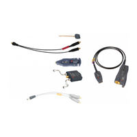
Keysight Technologies N5425B User Manual (182 pages)
Probe Amplifiers and Probe Heads
Brand:
Keysight Technologies
| Category:
Amplifier
| Size: 15 MB
Table of Contents
Table of Contents
3
1 MX0020A/21A/22A/24A/25A Probe Amplifiers - Overview
9
Introduction
10
Infiniimax Ultra Series Probe Amplifiers Key Features
12
Compatibility with Keysight Oscilloscopes
14
2 Compatible Probe Heads and Accessories - Overview
15
Supported Probe Heads for Infiniimax Ultra Series Probe Amplifiers
16
Infiniimax Ultra Series Probe Family Diagram
17
When to Use Which Recommended Probe Head
18
Other Recommended Accessories and Kits
21
N5450B Extreme Temperature Cable Extension Kit
21
N2880A Infiniimax In-Line Attenuator Kit
21
N2881A Infiniimax DC Blocking Capacitors
22
MX0102A Soldering Toolkit
22
N2852A Autoprobe II to Autoprobe III Adapter
25
Performance Verification and Deskew Fixture Kits
25
N5448B (25Cm) / N2823A (1M) Coaxial Phase Matched Cable Pair
26
N2812B (1M) High Performance Input Cable
27
E2669B Differential Connectivity Kit
27
3 Safety and Regulatory Information
31
Safety Checks and Warnings
32
4 Proper Handling of Probe Amplifier and Probe Heads
36
Avoiding Damage and Costly Repairs
36
Using a Static-Safe Workstation
36
Probe Amplifier and Probe Heads Handling Precautions
38
Precautions for the Probe Amplifier
38
Precautions for the Probe Cable
38
Precautions While Connecting and Disconnecting Probe Heads
39
Safely Connecting/Disconnecting the Probe Amplifier and Oscilloscope
39
Safely Connecting/Disconnecting the Probe Amplifier and Probe Head
39
Moving the Probing Setup to Different Probing Locations
39
Strain Relieving Techniques for Probe Heads
41
Tack-Putty
42
Low-Temperature Hot Glue
42
Velcro Pads
43
Tips for Soldering Probe Heads
44
Cleaning
45
5 Characteristics and Specifications
47
Infiniimax Ultra Series Probe Amplifiers Warranted Specifications
48
Infiniimax Ultra Series Probe Amplifier Characteristics
49
Infiniimax Ultra Probe Heads Characteristics
51
Environmental and General Characteristics
52
6 MX0100A Infiniimax Micro Probe Head
53
Overview
54
MX0100A Probe Head Kit Components
55
Connecting the MX0100A Probe Head to DUT
55
Infiniimode Capable
55
MX0100A Dimensions
55
MX0100A Input Impedance
57
Setting up and Using the MX0100A Probe Head
60
Trimming the Lead Wires of MX0100A Probe Head
60
Soldering an MX0100A Probe Head to DUT
61
Attaching Ground Lead Wires to an MX0100A Probe Head
63
Maintaining the MX0100A Probe Head
64
MX0100A Probe Head Handling Precautions
64
Replacing the MX0100A Probe Tip Lead Wires
67
Extreme Temperature Testing with the MX0100A Probe Head
70
7 MX0106A Infiniimax Ultra Differential Solder-In Probe Head
72
Overview
72
Infiniimode Capable
72
MX0106A Probe Head Supplied Accessories
72
MX0106A Dimensions
72
MX0106A Input Impedance
74
Setting up and Using the MX0106A Probe Head
77
Adjusting the Spacing between MX0106A Wires
77
Installing / Replacing the MX0106A Probe Head Wire Leads
77
Connecting the MX0106A Probe Head to DUT
81
Soldering the MX0106A Probe Head to DUT
81
Extreme Temperature Testing with the MX0106A Probe Head
82
8 N2839A Infiniimax II Browser Probe Head
84
Overview
84
N2839A Browser Probe Head Components
84
N2839A Supplied Accessories
84
N2839A Dimensions
85
N2839A Input Impedance
86
Using the N2839A Browser Probe Head
89
Adjusting Spacing between the Browser Tips
89
Hands-Free Probing
89
Maintaining the N2839A Probe Head
91
N2839A Probe Head Handling Precautions
91
Location of Serial Number
91
Replacing the Browser's Tips
92
9 MX0105A Infiniimax Ultra Differential SMA Probe Head
96
Overview
96
MX0105A Probe Head Components
96
Infiniimode Capable
97
MX0105A Dimensions
98
MX0105A SPICE Subcircuit Data
99
MX0105A Input Return Loss (S11)
100
10 N5425B Infiniimax Differential ZIF Probe Head
101
Overview
102
Supported ZIF Tips
102
N5425B Probe Head and ZIF Tips Dimensions
104
N5425B Input Impedance
106
SPICE Model of N5425B Probe Head with N5426A ZIF Tip Attached
107
SPICE Deck of N5425B Probe Head with N5426A ZIF Tip Attached
108
SPICE Model of the N5426A ZIF Tip
110
SPICE Deck of N5426A ZIF Tip
111
Using the N5425B Probe Head with N5426A ZIF Tips
113
Using the N5425B Probe Head with N2884A Fine Wire ZIF Tip
118
Maintaining the N5425B Probe Head
125
Fine Wire ZIF Tips Handling Precautions
125
11 Configuring Infiniium Software for Infiniimax Ultra Series Probe Amplifiers and Probe Heads
127
Selecting Components Used in the Probing Setup
128
Configuring Offset Behavior
131
Calibrating Your Infiniimax Ultra Probe
133
Calibration Overview
133
Sequence of Calibration
133
Before You Start Calibration
133
Performing DC Gain / Offset and Skew Calibration
134
Choosing the Probe Response Option
139
What Is Probe Response Correction
139
Available Probe Response Options
139
Source Estimate Option Availability
140
How to Change Probe Response Option
140
How to Determine the Currently Active Probe Response Option
141
Examples
141
12 Making Measurements
143
Measurement Modes - Overview
144
Orientation of the Probe Head
145
Probing Single-Ended Signals
146
Scenario 1: Using the Differential or Differential Source Estimate Measurement Mode
146
Scenario 2: Using the Single-Ended a or Single-Ended B Measurement Mode (Infiniimode)
147
Probing Differential Signals
148
Scenario 1: Using the Differential or Differential Source Estimate Measurement Mode
148
(Non-Infiniimode)
148
Scenario 2: Using the Differential Measurement Mode (Infiniimode)
149
Making Infiniimode Measurements
150
What Is Infiniimode
150
How Infiniimode Works
150
Infiniimode Capable Probe Amplifiers and Probe Heads
151
Infiniimode Measurements Setup
151
Attaching Ground Lead Wires to an Infiniimode Capable Probe Head
152
Infiniimode Measurements and Available Bandwidth
155
Extreme Temperature Probing
156
Infiniimax Ultra Probe Heads Supporting Extreme Temperature Testing
156
Probe Heads Discoloration
156
Cautions Associated with Extreme Temperature Testing
157
Probing Ungrounded Devices
158
Blocking out the DC Component of the Input Signal
159
13 Infiniimax Ultra Series Probe Amplifiers and Probe Heads System Responses
161
Typical Corrected System Frequency Response
162
Typical Step Response of Corrected System
163
Typical CMRR
164
14 Performance Verification
168
Before You Start
168
Recommended Test Interval
168
To Test Bandwidth
169
Required Test Equipment
169
Procedure
170
Performance Test Record
175
Advertisement
Advertisement
Related Products
Keysight Technologies N4985A-P25
Keysight Technologies N4985A-P15
Keysight Technologies N4985A-S30
Keysight Technologies N4985A-S50
Keysight Technologies Keysight N5470A
Keysight Technologies N5224A
Keysight Technologies N5241BU-617
Keysight Technologies N5173B
Keysight Technologies N5221/2A Series
Keysight Technologies N5256AW08
Keysight Technologies Categories
Measuring Instruments
Test Equipment
Control Unit
Portable Generator
Power Supply
More Keysight Technologies Manuals
Login
Sign In
OR
Sign in with Facebook
Sign in with Google
Upload manual
Upload from disk
Upload from URL