Table of Contents
Advertisement
Quick Links
Advertisement
Table of Contents

Related Manuals for Keysight Technologies M9379A


Summary of Contents for Keysight Technologies M9379A
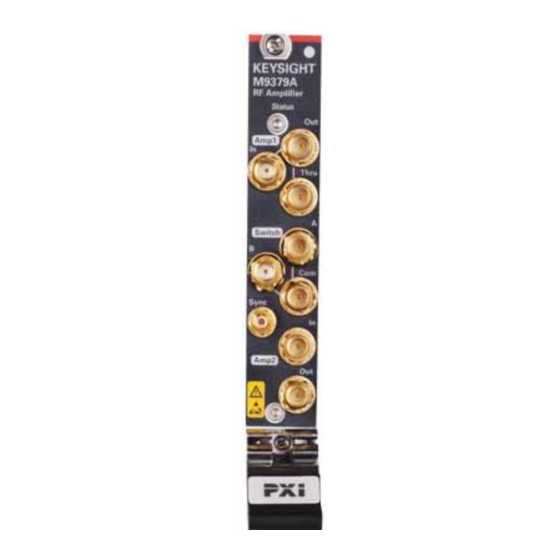
- Page 1 Keysight M9379A PXIe RF Amplifier Startup Guide...
- Page 2 Notices Manual Part Number Restricted Rights Legend M9379-90000 If software is for use in the performanc © Keysight Technologies, Inc. e of a U.S. Government prime contract Print Date 2015-2016 or subcontract, Software is delivered and licensed as “Commercial comp...
-
Page 3: Table Of Contents
Contents 1 ..........Getting Started Introduction Related Documentation STEP 1. - Page 4 Contents...
-
Page 5: Getting Started
Network Analyzer (VNA). When combined with the M9377A Direct Receiver Access Module and the M9378A high-power Coupler Module for network analysis, the M9379A’s internal amplifier (Amp1) can improve the noise floor of the measurement system. For example, the typical dynamic range can be reached to xx dB with the VNA system, making an ideal solution for high-rejection filter measurements. -
Page 6: Step 1. Unpack And Inspect The Rf Amplifier Modules
Getting Started STEP 1. Unpack and Inspect the RF Amplifier Modules STEP 1. Unpack and Inspect the RF Amplifier Modules The RF amplifier module is shipped in materials which prevent damage from static. The modules should only be removed from the packaging in an anti-static area ensur- ing that correct anti-static precautions are taken. -
Page 7: Inspect For Damage
Getting Started STEP 1. Unpack and Inspect the RF Amplifier Modules Inspect for Damage After unpacking a RF amplifier module, inspect it for any shipping damage. Report any damage to the shipping agent immediately, as such damage is not covered by the warranty. To avoid damage when handling the RF amplifier module, do not touch exposed connector pins. -
Page 8: Step 2. Check The Shipment
Getting Started STEP 2. Check the Shipment STEP 2. Check the Shipment The M9379A consists of several modules, cables and dividers. Use the Contents List in the shipping container to verify the completeness of your shipment. If not complete, refer to... -
Page 9: Step 3. Install The Rf Amplifier Modules
Getting Started STEP 3. Install the RF Amplifier Modules STEP 3. Install the RF Amplifier Modules This RF amplifier module can be used in a chassis with a PXIe, or PXI-H chassis slots. Recommended Best Practices to Ensure Proper and Safe Module Operating Conditions •... -
Page 10: Installation Procedure
Getting Started STEP 3. Install the RF Amplifier Modules • Torque driver (for use with socket adapter), set to 8 in-lb (0.91 N.m) - not supplied. • Cable removal tool (part number 5002-3361) - supplied. • Torque Wrench for SMA, set to 8 in-lb (0.91 N.m) - not supplied. •... - Page 11 Getting Started STEP 3. Install the RF Amplifier Modules 6. Holding the module by the injector/ejector handle, slide it into a slot, as shown in callouts 4 – 6 in Figure 1-3 on page a. Install the module into the slot of the chassis by placing the module card edges into the front module guides (top and bottom).
- Page 12 Getting Started STEP 3. Install the RF Amplifier Modules When connecting or disconnecting a cable to the module, do not touch the end of the cable. Doing so may damage the module by electrostatic discharge (ESD).
-
Page 13: Step 4. Install The Software
Getting Started STEP 4. Install the Software STEP 4. Install the Software System Requirements Topic Windows 7 and Vista Requirements Operating system Windows 7 (32 bit and 64 bit) or Windows 8.1 (32-bit and 64-bit) or Windows 10 (32-bit and 64-bit) Processor speed 1.5 GHz dual core (x86 or x64) minimum... -
Page 14: Power Up The Controller
This software must be installed first. Version 17.1 (or newer) of the Keysight IO Libraries Suite is required. • If you are using the M9379A as standalone, install the M9379A driver fr Keysight.com. The M9379A driver is available at http://www.keysight.com/support/m9379a. •... - Page 15 Suite CD included with your shipment, or the downloadable file at www.keysight.com/find/iosuite. Follow the installer prompts to install the IO libraries. 2. If you use M9379A as standalone, install the M9379A RF amplifier module driver: a. Using the downloadable file at http://www.keysight.com/support/m9379a, launch the installer.
- Page 16 Getting Started STEP 4. Install the Software e. Power up the remote controller PC. Check for software updates at: http://www.keysight.com/support/m9379a.
-
Page 17: Getting Help With Your Rf Amplifier Module
Use the Help System to quickly reference programming and user documentation To access Help: • If you use the M9379A as standalone, — On your PC screen, click the M9379 SFP icon. — Click Help. • If you use the M9379A with M9485A, —... -
Page 18: Contacting Keysight
Getting Help with Your RF Amplifier Module Contacting Keysight Contacting Keysight Assistance with test and measurements needs and information on finding a local Keysight office are available on the Web at: www.keysight.com/find/assist. If you do not have access to the Internet, please contact your Keysight field engineer. - Page 19 This information is subject to change without notice. © Keysight Technologies 2015-2016 *M9379-90000* www.keysight.com...
Need help?
Do you have a question about the M9379A and is the answer not in the manual?
Questions and answers