Upright MX15 Service & Parts Manual
Aerial work platform
Hide thumbs
Also See for MX15:
- Service manual (90 pages) ,
- Operator's manual (64 pages) ,
- Operator's manual (10 pages)
Table of Contents
Advertisement
Advertisement
Table of Contents
Troubleshooting

Related Manuals for Upright MX15


Summary of Contents for Upright MX15
- Page 1 060569-004...
- Page 2 SERVICE & PARTS MANUAL MX15/19 Aerial Work Platforms Serial Numbers 14000 to Current When contacting UpRight for service or parts information, be sure to include the MODEL and SERIAL NUMBERS from the equipment nameplate. Should the nameplate be missing, the SERIAL...
- Page 3 Indicates a potentially hazardous situation which, if not avoided, could result in severe injury or death. C A U T I O N Indicates a potentially hazardous situation which, if not avoided, may result in minor or moderate injury. NOTE: Gives helpful information. 060569-004 MX15/19 Page i...
- Page 4 Please understand that these warnings cannot cover all conceivable ways in which service, whether or not recommended by UpRight, Inc., might be done, or of the possible hazardous consequences of each conceivable way, nor could UpRight, Inc.
-
Page 5: Table Of Contents
Wire Color ..............3-1 060569-004 MX15/19 Page iii... - Page 6 3.4 UpRight Connectors ........
- Page 7 Checking Pump Pressures ........... . 4--2 4.3 Upright Motor Controller Diagnostics....... . 4--3 4.4 Measured Voltage at I/O Board .
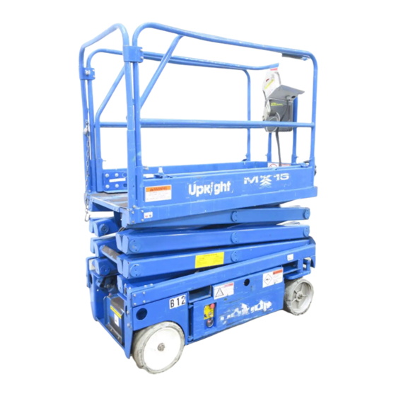
- Page 8 Section 1 Introduction Figure 1-1: MX15/19 Work Platform ......1-1 Section 2 Operation and Specifications Figure 2-1: Chassis Controls .
- Page 9 Figure 5-4: Plug Diagram ........5-7 060569-004 MX15/19 Page vii...
- Page 10 Hydraulic Schematic 065615-023 ........... . . 5-4 060569-004 Page viii MX15/19...
- Page 11 Table of Contents - List of Tables OTES 060569-004 MX15/19 Page ix...
- Page 12 Table of Contents - List of Tables OTES 060569-004 Page x MX15/19...
-
Page 13: Introduction
URPOSE The purpose of this service and parts manual is to provide instructions and illustrations for the operation and maintenance of the MX15/19 manufactured by UpRight, Inc. of Selma, California. COPE The manual includes procedures for proper operation, maintenance, adjustment, and repair of the MX15/19 as well as recommended maintenance schedules and troubleshooting. -
Page 14: Chassis
Introduction 1.2 - General Description HASSIS The chassis is a structural frame that supports all the components of the MX15/19 work platform. The platform is raised and lowered using a scissors mechanism. Lift is achieved using a single stage cylinder. - Page 15 NEVER recharge battery near sparks or open flame; batteries that are being charged emit highly explosive hydro- gen gas. AFTER USE secure the work platform against unauthorized use by turning key switch off and removing key. NEVER replace any component or part with anything other than original UpRight replacement parts without the manufacturer’s consent. 060569-004...
-
Page 16: Operation And Specifications
Operation and Specifications 2.1 - Introduction 2.1 I NTRODUCTION This manual covers all models of the MX15 and MX19 Self-Propelled Elevating Work Platforms. This manual must be stored on the machine at all times. 2.2 P PERATION AFETY NSPECTION Carefully read, understand and follow all safety rules, operating instructions, labels, and the Scaf- fold Industry Association’s MANUAL OF RESPONSIBILITIES. -
Page 17: Operation And Specifications
23. Push the Platform Emergency Stop Switch to check for proper opera- Drive/Lift tion. All machine functions should Platform Emergency Stop Switch Switch be disabled. Pull out the Platform Emergency Stop Switch to resume. 060569-004 MX15/19 Page 2-3... -
Page 18: Operation
4. If the machine is not level, the tilt alarm will sound and the machine will not lift or drive. If the tilt alarm sounds, the platform must be lowered and the machine moved to a firm, level surface before attempting to re-elevate the platform. 060569-004 Page 2-4 MX15/19... -
Page 19: Travel With Platform Elevated
1. Ensure that the platform is fully lowered. 2. Park the machine on a firm, level surface, preferably under cover, secure against vandals, children and unauthorized operation. 3. Turn the Chassis Key Switch to OFF and remove the key to prevent unauthorized operation. 060569-004 MX15/19 Page 2-5... -
Page 20: Parking Brake Release
Both the MX15 and MX19 may be forklifted from the rear end of the machine between the wheels. The MX15 may also be forklifted from the side, using the forklift pockets shown in the diagram. -
Page 21: By Truck
1. While holding the Brace, slowly raise the platform, using the Chassis Controls until the end of the Scissor Arm Weldment clears the Scissor Brace. 2. Rotate the Scissor Brace forward to rest on the Chassis. 3. Push the Chassis Lift/Lower Switch to LOWER and completely lower the platform. 060569-004 MX15/19 Page 2-7... -
Page 22: Battery Maintenance
D A N G E R Always replace batteries with UpRight batteries or manufacturer approved replacements weighing 62 lbs. (28 kg) each. • Check the battery fluid level daily, especially if the work platform is being used in a warm, dry climate. - Page 23 DO NOT leave the charger plugged in for more than 48 hours, as permanent damage to the batteries may occur. NOTE: The battery charger circuit must be used with a GFI (Ground Fault Interrupt) outlet. DO NOT operate the machine while the charger is plugged in. 060569-004 MX15/19 Page 2-9...
-
Page 24: Figure 2-9: Label Installation
Figure 2-9: Label Installation Ref. 065612-030, 065712-030 MXSeries label Installation: These labels shall be present and in good condition before operating the work platform. Be sure to read, understand and follow these labels BEFORE operating the work platform. 060569-004 Page 2-10 MX15/19... - Page 25 Operation and Specifications 2.5 - Maintenance OTES 060569-004 MX15/19 Page 2-11...
-
Page 26: Preventative Maintenance
Always block the elevating assembly whenever it is necessary to perform maintenance while the platform is elevated. The preventative maintenance checklist has been designed for machine service and mainte- nance. Please photocopy the following page and use the checklist when inspecting the machine. 060569-004 Page 2-12 MX15/19... -
Page 27: Preventative Maintenance Key
Check for peeling, missing, or unreadable Labels Pump Daily Check for leaks at mating surfaces labels & replace Check for hose fitting leaks Daily Check mounting bolts for proper torque Drive Check for operation and leaks Daily Motors 060569-004 MX15/19 Page 2-13... -
Page 28: Specifications
Operation and Specifications 2.7 - Specifications 2.7 S PECIFICATIONS ITEM MX15 MX19 Platform Size (Inside minimum) Standard w/Deck 22.5 in. x 100 in. (.57 m x 2.54 m) 22.5 in. x 100 in. (.57 m x 2.54 m) Maximum Platform Capacity Standard w/Deck Extension 550 lbs. -
Page 29: Maintenance
6 11 29 - means 1996, month 11 (November), day 29. uses a ten digit code: Plant, Year, Month, Day. ARKER i.e.: XXXX 6 11 29 - means Plant XXXX, 1996, month 11 (November), day 29. stamps month, day and year on each hose. AYCO 060569-004 MX15/19 Page 3-1... -
Page 30: Special Tools
(UpRight P/N 030898-000) • Inclinometer (UpRight P/N 010199-000) 3.4 U IGHT ONNECTORS UpRight connectors are designed so that connector parts, contacts or electrical cables may be replaced without replacing the entire connector. Figure 3-1: UpRight Connector Kit Small Kit Large Kit... -
Page 31: Female Connector (Receptacle)
4. Replace or recrimp the wires and contacts. Refer to “Crimping” procedure. ELEASING OCKING INGERS Figure 3-3: Locking Finger, UpRight Connector 1. The Locking Fingers can be released following the removal of the Locking Wedge of either the male or female connector. -
Page 32: 3.5 - Supporting The Elevating Assembly
4. Push the Chassis Lift Switch to UP and elevate the platform approximately 7 feet (2.1 m) for the MX15 or 9 feet (2.7 m) for the MX19. 5. Rotate the Scissor Brace towards the rear, holding it perpendicular to the scissor tube. -
Page 33: Battery Maintenance
Wash hands after use. Battery fluid is highly corrosive. Thoroughly rinse away any spilled fluid with clean water. D A N G E R Always replace batteries with UpRight batteries or manufacturer approved replacements weighing 62 lbs. (28 kg) each. ATTERY NSPECTION AND LEANING Check battery fluid level daily, especially if the work platform is being used in a warm, dry climate. -
Page 34: Battery Cell Equalization
Do not check the specific gravity in a cell to which water has just been added. If there is not enough electrolyte in a fully charged cell to obtain a sample for the hydrometer, add water and continue charging for one to two hours to adequately mix the water and electrolyte. 060569-004 Page 3-6 MX15/19... -
Page 35: 3.7 - Switch Adjustments
Level Sensor Circuit when the platform is elevated.The switch is located on the left side of the chassis at the rear of the machine. The down limit adjustment for MX15 35 inches (89cm); 45 inches (114cm) for the MX19. -
Page 36: Up Limit Switch
2. Remove and replace parts as Rocker Pin needed. Refer to Section 6 for Rocker, Steering repair parts numbers. Right Handle Half Steering Switch (2) Switch, Interlock Left Handle Half Boot, Handle Lever, Interlock Hall Effect Device 060569-004 Page 3-8 MX15/19... -
Page 37: 3.8 - Motor Controller And I/O Board Dip Switch Settings
Switches 1 and 2 should not be changed. Switches 3 and 4 work together to deter- mine the optional alarm settings Result Down alarm only Down and Reverse alarm Drive and Down alarm All Motion alarm Part Serial 060569-004 MX15/19 Page 3-9... -
Page 38: Hydraulic Oil Tank And Filter
Do not fill above the maximum line on the tank. Hydraulic tank has a 3.4 gal. (12.9 liter) capacity. 9. Operate all machine functions and recheck the fluid level. Add fluid if necessary. 060569-004 Page 3-10 MX15/19... -
Page 39: 3.10 - Hydraulic Pump
3. Remove the plugs from the hose assemblies and connect to the drive motor. 4. Lift the platform with the jack and remove jack stands, then lower the jack and remove. Oper- ate the drive system and check for leaks. 060569-004 MX15/19 Page 3-11... -
Page 40: Lift Relief Valve
6. Slowly turn the Main Relief Valve adjusting screw clockwise to increase the pressure until the gauge reads 3500 psi (241 bar) for the MX19, or 2500 psi (172 bar) for the MX15. 7. Tighten locknut or replace Main Relief Valve cover and torque to 6 ft/lbs (8 Nm.). ELIEF ALVE 1. -
Page 41: Counterbalance Valves
6 ft/lbs (8 Nm.). Remove blocks and lower the work platform to the ground. 11. Remove the gauge from the gauge port and reinstall cap. 12. Check for proper operation of the drive system and brake. 060569-004 MX15/19 Page 3-13... -
Page 42: Hydraulic Manifold
3. Connect hydraulic hoses. Be certain to tighten hoses to manifold. 4. Operate each hydraulic function and check for proper function and leaks. 5. Check the level of the hydraulic fluid in the tank. 6. Adjust all hydraulic pressures according to instructions on Page 3-12. 060569-004 Page 3-14 MX15/19... -
Page 43: Figure 3-18: Hydraulic Manifold
8. FITTING 8MB-8MJX 21. FITTING GAUGE 9. RELIEF VALVE, STEERING--1200 PSI (83 22. CHECK VALVE BAR) 23. DRIVE SOLENOID W/ COILS 10. RELIEF VALVE, MAIN--3000 PSI (207 BAR) 24. FITTING, HEX PLUG 9MM 11. LIFT SOLENOID 060569-004 MX15/19 Page 3-15... -
Page 44: Brake Cylinder
2. Install the piston onto the shaft. 3. Install the headcap on the shaft. 4. Install the spring. 5. Lubricate the piston seal with clean hydraulic fluid and install the shaft assembly in the inner cylinder barrel. 6. Install the snap ring. 060569-004 Page 3-16 MX15/19... -
Page 45: Figure 3-20: Brake Cylinder Assembly
25% (14°) grade. If they do not, tighten the adjustment bolt until they do. Secure the bolt with the locknut. 6. Check for leaks. 060569-004 MX15/19 Page 3-17... -
Page 46: Disassembly
3. Check the inside surface of the cylinder barrel for scoring or excessive wear. 4. Check the piston and headcaps for scoring or excessive wear. 5. Inspect the surface of the shaft for scoring or excessive wear. 060569-004 Page 3-18 MX15/19... -
Page 47: Assembly
3. Seal tings. 4. Wiper 4. Operate the steering circuit several times 5. Wear Ring 6. Seal throughout its entire range of travel to Seal Kit Part Number expel trapped air, then check for leaks. 065371-011 060569-004 MX15/19 Page 3-19... -
Page 48: Removal
1. Position the cylinder assembly in the chassis. Insert the pivot pins and secure with new cot- ter pins. 2. Connect the hose assemblies to the fittings. 3. Operate the steering circuit several times throughout its entire range of travel to expel trapped air, then check for leaks. 060569-004 Page 3-20 MX15/19... - Page 49 Maintenance 3.16 - Depression Mechanism Cylinder OTES 060569-004 MX15/19 Page 3-21...
-
Page 50: Disassembly
6. Unplug hydraulic hoses and attach to the cylinder. 7. Replace hydraulic fluid removed from lift cylinder. 8. Test with weight at rated platform load to check system operation. Check for leaks and level of fluid. 060569-004 Page 3-22 MX15/19... -
Page 51: Figure 3-24: Lift Cylinder
Maintenance 3.17 - Lift Cylinder Figure 3-24: Lift Cylinder 1. Lift Cylinder 2. Pivot Pit 3. Capscrew and Locknut 4. Solenoid 5. Down Orifice 6. Spring 060569-004 MX15/19 Page 3-23... -
Page 52: Disassembly
5. Set the brushes to final position as shown in Figure B. 6. Place the complete stator down over the vertical armature and into position on the commuta- 060569-004 Page 3-24 MX15/19... -
Page 53: Figure 3-25: Electric Motor
Figure 3-25: Electric Motor Ammeter Power Motor Supply Voltage Meter Brushes raised with Brushes and the springs in locked springs in their position on the side final position of the brush Keep fingers clear of this space. 060569-004 MX15/19 Page 3-25... -
Page 54: 3.19 - Torque Specifications
PECIFICATIONS YDRAULIC OMPONENTS NOTE: Always lubricate threads with clean hydraulic oil prior to installation. Use the following values to torque hydraulic components used on UpRight work platforms. Table 3-1: Torque Specifications for Hydraulic Components Type: SAE Part Series Cartridge Poppet... -
Page 55: Table 3-3: Torque Specifications For Metric Fasteners, U.s. Customary Units
256,808 1233 206,550 285,728 1157 1543 333,923 1352 1803 252,450 1136 1515 349,223 1572 2095 408,128 1837 2450 312,300 1546 2061 432,015 2138 2851 504,885 2500 3332 367,650 1985 2647 508,582 2746 3662 594,368 3210 4279 060569-004 MX15/19 Page 3-27... - Page 56 Maintenance 3.19 - Torque Specifications OTES 060569-004 Page 3-28 MX15/19...
-
Page 57: Introduction
3-4. Unplug the machine or disconnect the battery when replacing or testing the continuity of any electrical component. Tel: 1-559-891-5200 IGHT FAX: 1-559-891-8931 Tel: +353-1-202-4100 IGHT RELAND FAX: +353-1-202-4105 060569-004 MX15/19 Page 4-1... -
Page 58: Special Tools
MX15/19. • Flow Meter with Pressure Gauge (UpRight P/N 067040-000) • 0-1000 psi (0-69 bar) Hydraulic Pressure Gauge with Adapter Fittings (UpRight P/N 014124- 010) • 0-3000 psi (0-207 bar) Hydraulic Pressure Gauge with Adapter Fittings (UpRight P/N 014124-030) •... -
Page 59: 4.3 - Upright Motor Controller Diagnostics
Troubleshooting 4.3 - Upright Motor Controller Diagnostics 4.3 U PRIGHT OTOR ONTROLLER IAGNOSTICS Batteries must be fully chargesd before troubleshooting. Check/Repair all connections before replacing any components Table 4-1: LED Fault Codes LASH EANING TATUS ORRECTIVE CTION Power to the controller and the LED on System is functional. -
Page 60: Measured Voltage At I/O Board
24 Volts = Line Contactor OFF / 0 Volts = Line Contactor ON 24 Volts = No Direction Solenoid Allowed / 0 Volts = Direction Solenoid Allowed to Activate Accelerator 3.5 Volts to 0 Volts / Minimum to Maximum Speed 060569-004 Page 4-4 MX15/19... - Page 61 Next, perform all machine functions until the red LED is illuminated. Determine which function activated the red LED and check all components that are active for that function. Figure 4-3: I/O Board Red LED Green LED 060569-004 MX15/19 Page 4-5...
-
Page 62: Electric
Interlock Switch--S7 PQ Control Handle--S8 Height Limit Switch--S9 Platform Steering Switch--S10 Tilt Sensor--SNSR Steering Solenoid (right)--SOL1A Steering Solenoid (left)--SOL1B Platform Lift Solenoid--SOL2A Down Solenoid--SOL2B Depression Mechanism Extension Solenoid--SOL3A Depression Mechanism Retraction Solenoid--SOL3B Reverse Solenoid--SOL4A Forward Solenoid--SOL4B 060569-004 Page 4-6 MX15/19... -
Page 63: Hydraulic
Return Filter--FL2 Drive Motors (2)--MOT Pump--PMP Main Relief Valve--RV3 Steering Relief Valve--RV1 Lift Relief Valve--RV2 Orofice--OR Tank--TNK Steering Right/Left Valve--V1 Lift Valve--V2A Down/Emergency Lowering Valve--V2B Depression Mechanism Retract Valve--V3B Depression Mechanism Extend Valve--V3A Forward/Reverse Valve--V4 Counterbalance Valve--V5 060569-004 MX15/19 Page 4-7... - Page 64 Troubleshooting 4.7 - Hydraulic 060569-004 Page 4-8 MX15/19...
-
Page 65: Schematics
Legend: Electrical Schematic 065616-024 ..... . . 5-2 Legend: Hydraulic Schematic 065615-030..... . . 5-5 060569-004 MX15/19 Page 5-1... -
Page 66: Electrical Schematic
Solenoid to reverse Lift/Drive Activates lift or drive Platform Controls SOL4B Forward Shifts forward/reverse valve Selector Switch functions Hydraulic Manifold Solenoid to forward Platform Down Cuts out high speed drive Linkage Switch when platform is elevated 060569-004 Page 5-2 MX15/19... -
Page 67: Figure 5-1: Electrical Schematic
Schematics 5.2 - Electrical Schematic Figure 5-1: Electrical Schematic SOL1A SOL1B SOL2A SOL4A SOL4B SOL3A SOL2B SNSR SOL3B SOL3B CONTROL HANDLE 060569-004 MX15/19 Page 5-3... -
Page 68: Hydraulic Schematic
Provides oil control for DM Depression Mechanism Mechanism Cylinder Retract Valve (2) Forward/Reverse Provides oil control for Hydraulic Manifold Valve drive or lift functions Prevents machine from Counterbalance running away on slopes; Hydraulic Manifold Valve (2) cushions stops 060569-004 Page 5-4 MX15/19... -
Page 69: Figure 5-2: Hydraulic Schematic
Schematics 5.3 - Hydraulic Schematic Figure 5-2: Hydraulic Schematic 060569-004 MX15/19 Page 5-5... -
Page 70: Figure 5-3: Valve Diagram
Schematics 5.3 - Hydraulic Schematic Figure 5-3: Valve Diagram 060569-004 Page 5-6 MX15/19... -
Page 71: Figure 5-4: Plug Diagram
Schematics 5.3 - Hydraulic Schematic Figure 5-4: Plug Diagram #2 Plug #2 #4 Plug #4 #6 Plug #6 #8 Plug #8 060569-004 MX15/19 Page 5-7... - Page 72 Schematics 5.3 - Hydraulic Schematic OTES 060569-004 Page 5-8 MX15/19...
-
Page 73: Illustrated Parts Breakdown
065612-030 ........6-32 Scissor Linkage Assembly, MX15 Label Installation, MX19 065605-020 . - Page 74 Illustrated Parts Breakdown - 6.1 - Introduction Final Assembly, MX15 065600-020 ITEM PART DESCRIPTION QTY. ITEM PART DESCRIPTION QTY. 062125-003 CABLE ASSY X 24 065601-020 BASIC ASSY 101182-002 CABLE ASSY W/ CONNECTOR 063944-001 CHARGER 010154-001 COVER BATTERY TERMINAL 066490-020 SWITCH ROLLER ASSY...
- Page 75 Illustrated Parts Breakdown - 6.1 - Introduction Drawing # 1 of 3 060569-004 MX15/19 Page 6-3...
- Page 76 Illustrated Parts Breakdown - 6.1 - Introduction Drawing # 2 of 3 060569-004 Page 6-4 MX15/19...
- Page 77 Illustrated Parts Breakdown - 6.1 - Introduction Drawing # 3 of 3 060569-004 MX15/19 Page 6-5...
- Page 78 065798-000 MOUNTING PLATE BALLAST 062125-003 CABLE ASSY X 24 011252-048 SCREW HHC 1/4-20 UNC X 6 101182-002 CABLE ASSY X 18 019775-017 BAR 010154-001 COVER BATTERY TERMINAL 011254-020 SCREW HHC 3/8-16 X 2-1/2 029601-039 CONN RING 5/16 10-12 060569-004 Page 6-6 MX15/19...
- Page 79 Illustrated Parts Breakdown - 6.1 - Introduction Drawing # 1 of 3 060569-004 MX15/19 Page 6-7...
- Page 80 Illustrated Parts Breakdown - 6.1 - Introduction Drawing # 2 of 3 060569-004 Page 6-8 MX15/19...
- Page 81 Illustrated Parts Breakdown - 6.1 - Introduction Drawing # 3 of 3 060569-004 MX15/19 Page 6-9...
- Page 82 Illustrated Parts Breakdown - 6.1 - Introduction Basic Assembly, MX15 065601-020 ITEM PART DESCRIPTION QTY. 065602-020 CHASSIS ASS’Y 065605-020 SCISSOR ARM ASS’Y X15 066250-001 PLATFORM WELDMENT 065698-000 LOWER PIVOT PIN WELDMENT 065726-000 SLIDE PAD 065728-000 DECK BRACKET L.H. 065727-000 DECK BRACKET R.H.
- Page 83 Illustrated Parts Breakdown - 6.1 - Introduction 060569-004 MX15/19 Page 6-11...
- Page 84 011254-034 SCREW HHC 3/8-16UNC X 4 1/4 011254-014 SCREW HHC 3/8-16UNC X 1 3/4 011240-006 WASHER 3/8 STD FLAT 011248-006 NUT HEX ESNA 3/8-16UNC 011829-022 CARRIAGE BOLT 1/4-20 X 2-3/4 PLATED 011248-004 LOCK NUT 1/4-20 065764-000 SCISSOR CHOCK WELDMENT X15/19 060569-004 Page 6-12 MX15/19...
- Page 85 Illustrated Parts Breakdown - 6.1 - Introduction 060569-004 MX15/19 Page 6-13...
- Page 86 05154-002 FILTER ELEMENT 063973-001 VALVE N.C. 120 065359-000 LADDER SUPPORT WELDMENT 066322-000 CYLINDER LINK 121 011254-008 SCREW HHC 3/8-16UNC X 1 066096-016 SCREW 1/2-13UNC SQ HD x 2 018183-058 TUBE 1-3/8 O.D. x 1/8 WALL x 5/8 LG 060569-004 Page 6-14 MX15/19...
- Page 87 Illustrated Parts Breakdown - 6.1 - Introduction Drawing # 1 of 3 060569-004 MX15/19 Page 6-15...
- Page 88 Illustrated Parts Breakdown - 6.1 - Introduction Drawing # 2 of 3 060569-004 Page 6-16 MX15/19...
- Page 89 Illustrated Parts Breakdown - 6.1 - Introduction Drawing # 3 of 3 060569-004 MX15/19 Page 6-17...
- Page 90 Illustrated Parts Breakdown - 6.1 - Introduction Scissor Linkage Assembly, MX15 065605-020 ITEM PART DESCRIPTION QTY. 065640-000 INNER ARM WELDMENT 065671-000 OUTER BEAM WELDMENT R.H. 065672-000 OUTER BEAM WELDMENT L.H. 065675-001 OUTER BEAM WELDMENT 065677-000 INNER CENTER BEAM WELDMENT 065687-000 CABLE GUIDE...
- Page 91 Illustrated Parts Breakdown - 6.1 - Introduction 060569-004 MX15/19 Page 6-19...
- Page 92 065722-000 INNER BEAM WELDMENT 065688-000 GUARD RIVET 065750-000 CYLINDER PIN WELDMENT 011248-006 LOCKNUT 3/8-16UNC HEX 012004-004 PLUG #4 012004-006 PLUG #6 065920-000 PIVOT PIN WELDMENT 066179-000 VALVE 011941-005 FITTING 6MB-6MJ ST 015919-001 ORIFICE 05133-000 SPRING 013919-009 CLAMP 060569-004 Page 6-20 MX15/19...
- Page 93 Illustrated Parts Breakdown - 6.1 - Introduction 060569-004 MX15/19 Page 6-21...
- Page 94 015752-000 HOURMETER 068807-010 REPLACEMENT KEY 066805-010 SWITCH CONTACT N.O. 068582-005 CIRCUIT BREAKER 065978-000 COVER 066805-011 SWITCH CONTACT BLOCK 011811-006 SCREW SLFTP F HWH 10-32 X 3/4 012798-000 SWITCH TOGGLE 066805-006 SWITCH HEAD MUSHROOM 029925-010 CONNECTOR CABLE 060569-004 Page 6-22 MX15/19...
- Page 95 Hydraulic Tank Assembly 101152-001 ITEM PART DESCRIPTION QTY. ITEM PART DESCRIPTION QTY. 011939-015 FITTING 8MP-8MJ 101056-001 TANK, HYDRAULIC 011939-015 FITTING, REDUCER 8MP-6MJ 021305-006 PLUG, MAGNETIC 068982-001 HYDRAULIC TANK LID 061818-000 STRAINER, SUCTION 011940-006 FITTING ELBOW, 4MP-6MJ 060569-004 MX15/19 Page 6-23...
- Page 96 064843-000 FLOW DIVIDER VALVE (1.0 GPM) 063973-001 2 POS POPPET VALVE W/ COIL 101120-033 COIL 012004-008 FITTING, #8 PLUG 063965-001 FITTING GAUGE 064841-000 CHECK VALVE 063923-021 3 POS - 4 WAY SOLENOID W/ COILS 020021-004 FITTING, HEX PLUG #4 060569-004 Page 6-24 MX15/19...
- Page 97 Illustrated Parts Breakdown - 6.1 - Introduction 060569-004 MX15/19 Page 6-25...
- Page 98 14 061789-017 HOSE ASSY 3/4 X 17 1/2 (12FJX-12MP) 15 064156-021 HOSE ASSY 1/2 X 42 (8FJX-8FJX) 17 107091-038 HOSE ASSY 3/16 X 38 (4FJX-4FJX90) 19 107091-032 HOSE ASSY 3/16 X 32 20 107091-037 HOSE ASSY 3/16 X 37 060569-004 Page 6-26 MX15/19...
- Page 99 Illustrated Parts Breakdown - 6.1 - Introduction 060569-004 MX15/19 Page 6-27...
- Page 100 FT 2.3 065512-017 HANDLE HALF, LEFT 011811-006 SCREW SLFTP 10-32 X 3/4 065512-018 BOOT, HANDLE 011761-004 SCREW MACH SLOTTED TRUSS HD #10-24 X 1/2 101240-000 CABLE ASSY CONTROLLER EURO 029925-010 CONN CABLE Drawing # 1 of 2 060569-004 Page 6-28 MX15/19...
- Page 101 Illustrated Parts Breakdown - 6.1 - Introduction Drawing # 2 of 2 060569-004 MX15/19 Page 6-29...
- Page 102 03570-000 RETAINING PIN ASSY 011253-018 SCREW 5/16-18 HHC X 2 1/4 066498-000 WELDMENT, GATE LATCH 011254-018 SCREW 3/8-16 HHC X 2 1/4 066257-007 WELDMENT SIDE RAIL 011248-006 NUT 3/8-16 HEX 066261-001 WELDMENT, END RAIL 065987-000 CAPLUG BEARING 060569-004 Page 6-30 MX15/19...
- Page 103 066195-000 PLATFORM ROLLER 011240-004 WASHER 1/4 FLAT 066407-011 BRACKET 011238-006 WASHER 3/8 LOCK 066256-000 WELDMENT ROLLER MOUNT 014996-020 WASHER SAE 1-1/4 ZINC PLATED 067185-000 WELDMENT DECK STOP 066260-001 WELDMENT EXT. RAIL X15 065988-099 TAPE UHMW 1" FT 3 060569-004 MX15/19 Page 6-31...
- Page 104 Illustrated Parts Breakdown - 6.1 - Introduction Label Installation, MX15 065612-030 ITEM PART DESCRIPTION QTY. ITEM PART DESCRIPTION QTY. 101222-004 LABEL CONTROLLER 061683-004 LABEL UPRIGHT 05221-000 LABEL BATTERY 061684-022 LABEL MX 15 014222-003-99 LABEL FORK-LIFT HERE 061683-014 LABEL UPRIGHT 063255-001...
- Page 105 Illustrated Parts Breakdown - 6.1 - Introduction 060569-004 MX15/19 Page 6-33...
- Page 106 010076-001 LABEL INST. 060577-004 ANSI MANUAL 061220-002 LABEL ANSI 010076-000 MANUAL CASE 101252-002 LABEL WHEEL MAX LOAD WHEEL 060570-004 USER MANUAL MX15/19 061205-005 NAME PLATE 011248-004 LOCKNUT 1/4-20UNC HEX 065368-000 TACK 011252-006 SCREW 1/4-20UNC HHC X 3/4 064444-000 LABEL USA...
- Page 107 Illustrated Parts Breakdown - 6.1 - Introduction 060569-004 MX15/19 Page 6-35...
- Page 108 065926-010 PLUG CONNECTOR 011254-018 SCREW HHC GRD5 3/8-16UNC X 2 1/4 068762-000 PIN CONTACT 011240-006 WASHER 3/8 STD FLAT 068764-000 PLUG SEALING 011248-006 NUT HEX ESNA 3/8-16 065926-015 RECEPTACLE CONNECTOR 068762-001 SOCKET CONTACT 030719-001 110 VAC BRACKET 060569-004 Page 6-36 MX15/19...
- Page 109 Illustrated Parts Breakdown - 6.1 - Introduction 060569-004 MX15/19 Page 6-37...
- Page 110 Illustrated Parts Breakdown - 6.1 - Introduction Hour Meter with Battery Low Voltage Indicator 066613-020 ITEM PART DESCRIPTION QTY. 029959-000 HR/LOW VOLTAGE IND. 060569-004 Page 6-38 MX15/19...
- Page 111 029452-099 WIRE, 16 AWG BLACK 4 FT 066807-002 HORN, 24 VDC CONTROLLER ASSY 066805-018 SWITCH, PUSH BUTTON 6E 011252-006 SCREW HHC 1/4-20 X 3/4 066805-010 CONTACT BLOCK NO 029620-002 CONNECTOR, BUTT 16-14 GA 029601-013 CONNECTOR, RING TERMINAL 060569-004 MX15/19 Page 6-39...
- Page 112 Illustrated Parts Breakdown - 6.1 - Introduction OTES 060569-004 Page 6-40 MX15/19...
- Page 113 060569-004...
- Page 114 UpRight, Inc. UpRight International Support Centre 1775 Park Street Selma, California 93662 Innsbruckweg 114 Call Toll Free in the U.S.A. 3047 AH Rotterdam TEL: 559/891-5200 1-800-926-LIFT Netherlands FAX: 559/891-9012 TEL: +31(0)10-238-0000 PARTS: 1-888-UR-PARTS PARTS FAX: 559/896-9244 FAX: +31(0)10-238-0001 Parts Tel: +31(0)10-490-8090...
Need help?
Do you have a question about the MX15 and is the answer not in the manual?
Questions and answers